It may sound paradoxical, but the improvements to the 16-bit platform that were illustrated in the previous article are the ones that would have brought the most benefits to the Amiga platform, firstly because they would have made it extremely competitive again even with the other consoles of the “16-bit generation”, and secondly (but not least) because they already contain almost everything needed to make it evolve later, also taking advantage of the higher operating frequencies (which in any case have already been taken up by the last line of innovations that were presented).
Left out is the question of the size of the “data bus” (inverted comma, because in this context it will always be understood as the amount of data that can be read or written for every single memory access that has been granted by the chipset), which will be the subject of this article as a major change (but obviously not the only one to be presented).
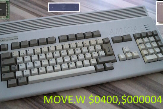
1992: the time of the Amiga 4000 and 1200
Two years after the 16-bit / 14Mhz chipset, the next 32-bit platform could have:
- 32-bit data bus, with access also in fast page mode to read two 32-bit data (thus 64 bits in all) in one slot (as always, this term means one memory access possibility);
- elimination of the Chip memory access block every two slots for 68020+ processors (so they can access using up to twice as many slots as the 16-bit chipset);
- packed/chunky graphics support in 15/16 bit (32 and 65 thousand colours), 24 (16 million colours) and 32 bit (as before, but with the addition of the alpha channel), and colour palette extended to 16 million;
- screens from 640×200/256 (NTSC/PAL) 32-bit up to 800×600 8-bit;
- Dual Playfield mode with two screens of 320×200 at 32 + 16 bits, and up to 640×400 at 8 + 8 bits;
- “agnostic” Blitter with regard to the size of the data “bus”, thus able to work with data of any size (up to 64 bits, in this case. So up to four times faster than the previous one, which was already twice as fast as the original chipset), and with packed/chunky 15/16 bit, 24 and 32 bit pixels;
- tracing lines with the Blitter using a texture in Chip memory (a line of bytes) for colours to be used for all traced points, when using packed/chunky modes;
- buffer for the Copper‘s instructions, using the larger data “bus”, in order to speed up execution;
- new format of Copper’s
WAITandSKIPinstructions to take into account the size of the screen; - the 32 sprites (they had been increased with the last 16-bit/14MHz extension) can now go up to 16 and 256 colours thanks to the new data “bus”;
- new format of sprite registers to be able to place them on larger screens, and allow for other changes (“flip” vertically, possibility of choosing any palette to use out of the two 256 colours available, suppression of control words);
- the 32 audio channels (also previously extended, as for sprites) can be up to 56kHz in frequency and with 16-bit samples, again with the new data “bus”;
- new audio registers format, to allow sample lengths greater than 128kB to be specified, expand volume to 256 levels for left and right output, and give the possibility to define more features;
- possibility of sampling from external audio sources;
- support for 2 and 4MB floppy disks;
- serial with FIFO buffer and dedicated DMA channels, so as to minimise character/byte losses and to free up the CPU almost completely;
- new 32-bit registers to directly address the two 256-colour palettes of 16 million, the 32 sprites (and even more with future extensions) and the 32 audio channels (and even more in the future) at full speed;
- up to 8MB of Chip memory addressable by the chipset.
On the surface it looks like a lot of stuff, but in reality much of the innovation comes directly from the ability to access up to 4 times more data than the previous generation (the 16-bit/14MHz one; which had already doubled the available memory bandwidth compared to the original chipset. So it comes to 8 times the bandwidth, in total): higher resolutions (even in Dual Playfield, which can also use packed/chunky modes), up to 64-bit Blitter (thus also faster, as already mentioned), faster Copper instructions, and support for 2MB and 4MB floppy disks all fall under the umbrella of immediately accessible changes thanks to the exploitation of the new data “bus” and buffers for the components that make full use of it.
More colourful sprites… and more
A similar consideration can be made for sprites. These, being able to read 32 or 64 bits instead of 16, can easily expand their colour range from the 4 colours they normally use. The logic of the new operation in this case is really trivial and fully natural with the operation of the chipset and the graphic objects themselves, but requires a little explanation to understand.
The 4 colours derive from the fact that, with the 16-bit bus, two 16-bit data are read, representing respectively the data of the first and second bitplane which, put together, constitute the 16-pixel row of the sprite. But if 32 bits are read at a time, we have twice as much data, which can be thought of as four 16-bit data/bitplanes (the first two coming from the first 32-bit value, and the other two from the second), and with four bitplanes we can display 16 colours. Using the same logic, reading two 64-bit data/bitplanes we have 8 16-bit data/bitplanes and, thus, 256 displayable colours.
One could also use the 32- and 64-bit data to enlarge the sprites, making them 32 and 64 pixels horizontally, but their use would be far more limited (and would increase the waste of memory and bandwidth), since they would remain 4-colour.
I shall never tire of repeating, in fact, that it is preferable, in general, to have smaller and much more colourful sprites, because they allow both better reuse of graphics (larger graphic objects can be obtained from the combination of many smaller sprites, some of which can draw on the same assets) and, above all, having more colours is decidedly more visually satisfying than the poverty of only 4 colours (which are actually three, because one is used for transparency).
The other changes to the sprites (flips, colour palette, etc.) will be covered in the last section, which concerns the new memory map, as the format of the new registers (which obviously include those of the sprites) will be shown.
The evolution of audio…
The same goes for audio: the biggest benefits come from the quadrupled bandwidth, compared to the previous chipset (16-bit/14Mhz), which allows both to double the operating frequency (reaching 56kHz maximum) and to have the coveted 16-bit samples, finally putting the platform back on track from this point of view and, indeed, going well beyond what the competition offers.
Mixing all these channels at 16 bits might seem excessive in terms of resources, but the path mapped out with the aforementioned chipset, as seen in the previous article, allows everything to be handled without requiring so many resources, apart from now using two DACs with higher precision so as to be able to achieve better reproduction quality, and extending the precision of the two adders that take care of the actual mixing (before sending the result to the two DACs).
The other changes (including sampling from an external source) depend mainly on the new registers, and will be covered in the appropriate section. Actually, there would also be room in the current registers (some words are unused), but the changes required would have been another patch on the old registers, while the new (not so much: it’s a natural evolution) format allows all the changes to be mapped in a simpler, more functional, and immediate way.
… and video
Going from 8-bit to 16-bit audio samples is a revolution, but certainly not as much as going from a 4096 to a 16 million colour palette: the impact is dramatically and pleasantly more perceptible. In ’92 it was certainly time for the Amiga to make the big leap as well, thanks both to the greater number of transistors available to “enlarge” the two 256-colour palettes, and to the support for the 24- and 32-bit packed modes, to which also the 16-bit packed/chunky modes (32 and 65 thousand colours) were now rapidly spreading (as a good compromise between number of colours and memory space occupied).
The biggest limitation used to be the low bandwidth available, but the increased frequency of the previous generation and, above all, the new data “bus” allow these modes to be used, albeit up to certain resolutions, of course (you can’t expect them for higher ones).
The implementation is not complicated, as it is an extension of what was already done to add the 8-bit packed/chunky mode, which introduced the use of single bytes to “address” pixel colours. The new 16-, 24- and 32-bit modes are a simple continuation of the same concept, but using two, three and four bytes respectively, with the further slight modification represented by the fact that the video chip is not forced to access the colour palette to finally derive the colour to be sent to the monitor/TV, but the colour is already directly available (although for the 16-bit modes it needs to be “adjusted” a little, to generate the relevant colours but at 24 bits).
The same, identical, discourse also applies to the Blitter’s support of these modes. A coprocessor which, having always operated with words (16 bits, two bytes) at a time, has never had any problems in this sense, apart from knowing what to do with those bits (and for this it is important to specify which type of packed/chunky format must be used by the data channels on which it operates). The discourse changes slightly to support 24- and 32-bit, but remains smooth thanks to the enlargement of the data “bus” to 32 and more bits.
Drawing lines: the harbinger to rotations, zooms, and… 3D!
One of the greatest limitations of the Blitter’s hardware line-drawing feature was that it could only draw them in a duo/monochrome manner: using only two colours (one for “full” pixels = with value 1 in bitplanes, and one for “empty” pixels = with value 0), or one (for “full” pixels: the empty ones would be “transparent”, thus leaving the background intact).
The aforementioned packed/chunky formats, on the other hand, allow this limitation to be easily overcome, since it is sufficient to have the source channel B point to the Chip memory area where the byte sequence with the colours to be loaded is located and use it as the individual pixels of the line are drawn. Normally, this channel does not load anything from memory, but its value is preset to directly specify the pattern of the graphics to be used cyclically (it repeats every 16 pixels) to set the “colour” (actually it is a matter of obtaining “full” or “empty”/”transparent” pixels, as already explained) of each pixel.
This trivial modification therefore makes it possible to obtain such a function, which on the surface may not seem very important, but which in reality can be exploited to finally implement a graphics primitive which is very onerous in terms of performance and for which the processor has always had to take responsibility: rotation. Obviously we are talking about rotation of an entire image. For example starting from this one:
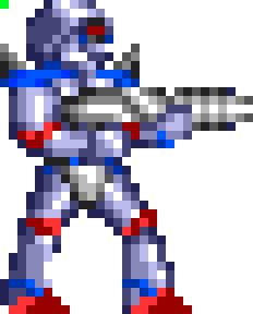
to obtain this other:
The basic idea is not complicated at all. In fact, all you have to do is start from the first line of the unrotated image, which will become the source of the B channel, and draw a line from the coordinates of the first point (highlighted in green in both images) that will be rotated (here you need the CPU to calculate its position, of course) and for the length of the image line. We then repeat the same process for the second row, calculating the first rotated point, and so on for all rows, and we are done!
With a similar procedure you can also implement the horizontal zoom, but in this case you need an additional register where you specify the zoom factor (a fixed-point value 8 + 8 = 16 bits: 8 bits for the integer part and 8 for the decimal part) to be used, which is equivalent to knowing how much to increment/forward the pointer of the B channel to load the next colour. In this case, the channel data register can be recycled (which with planar graphics was used to load the pattern with which to draw lines).
Internally, the Blitter will use an 8-bit register, initially set to zero, where it will store fractional values, so that it can accumulate values as it goes along. To be clear, it is as if the B channel pointer had been “enlarged” with an additional 8 bits that will contain the fractional part of the sum between the current pointer and the zoom factor, which is carried out each time we need to move on to the next pixel to be plotted.
This mechanism, as already mentioned, allows only the horizontal zoom to be implemented for a single line. It will be sufficient to process one line at a time of the image to be zoomed, in order to apply it to the entire image. To also zoom vertically, it will be sufficient for the processor to “steer” the tracing of the horizontally zoomed lines, but using a vertical zoom factor for the purpose. Finally, and applying both concepts, it will of course be possible to implement image rotation and zoom simultaneously.
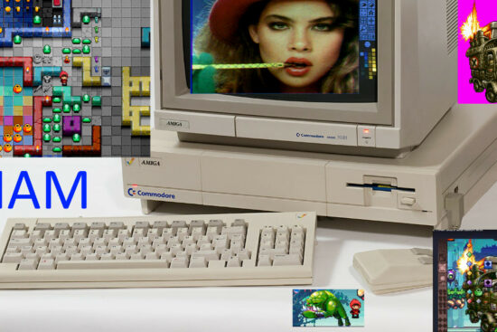
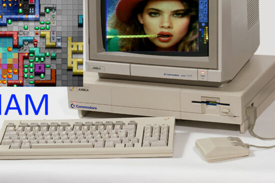
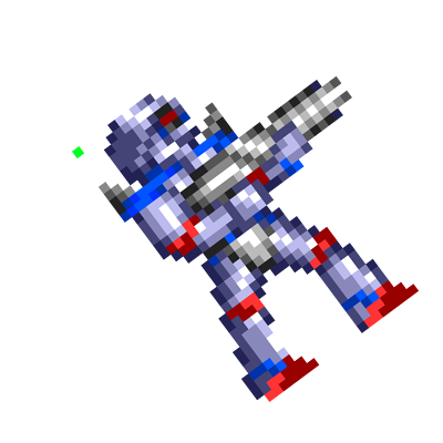
These are very important primitives, also used in games (but not only: think of the transposition of a matrix, for example), which were sorely missed on the Amiga. Even if they require processor support to coordinate all operations, line by line, they still represent a major step forward compared to the complete absence of hardware acceleration, and would have helped a lot in games like this one:
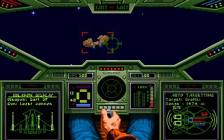
It should also be pointed out that it would be possible to use the same mechanism to help implement the first 3D games, also called 2.5D because they render the scene in partial 3D, using certain tricks to draw walls and floors, as for example in this case:
Everything would have been fine, in short, to try to help the platform that was generally equipped with cheap processors to save on production costs, and therefore could not rely on large computing power.
New format for Copper’s WAIT and SKIP instructions
Turning to the other coprocessor, some fairly important modifications are necessary to Copper due to the increase in screen resolution, which go well beyond those made available in the mid-1980s.
I report the format of its instructions (which consist of two words = 16 bits), as there are only three of them and they require little space for description:
| Bit 0 | Always set to 0 |
| Bits 11 – 1 | Address of destination register |
| Bits 15 – 12 | Number of 16-bit registers to be set |
| Bits 15 – 0 | 16-bit of data to be transferred (moved) to the destination register |
| Bit 0 | Always set to 1 |
| Bits 7 – 1 | Horizontal beam position (divided by 2) |
| Bits 15 – 8 | Vertical beam position |
| Bit 0 | 0 = WAIT, 1 = SKIP |
| Bits 7 – 1 | Horizontal position compare enable bits |
| Bits 14 – 8 | Vertical position compare enable bits |
| Bit 15 | The blitter-finished-disable bit |
Just for the sake of clarity and fairness, MOVE already incorporates the changes suggested in previous articles regarding the possibility of setting more than one register (in the original Amiga version it only allows this for one register).
The WAIT and SKIP instructions take care of waiting for a certain position of the electronic beam, respectively, or skipping the next instruction if it has already been passed. They can also take into account the state of the Blitter and wait until it has finished its work, or skip the next instruction if it has already finished.
There are a couple more things to point out. First, the horizontal resolution is halved, because the least significant bit is missing. Secondly, and this is the object of interest, there are only a few bits available (7 for the horizontal value and 8 for the vertical one) to specify any coordinate. For the horizontal value this is not a big problem (at least with the Amiga’s video signals), because it actually refers to the memory slot and not the actual coordinate, so the actual granularity horizontally ranges from 4 (low resolution) to 2 (high resolution) pixels.
The vertical one, on the other hand, coincides with the actual coordinate, and with video signals such as PAL (which has 256 visible lines, but another 56 not visible) this requires the use of two instructions for actual vertical coordinates exceeding 256. In fact, one must first add an instruction to wait for the end of line 255, and then add another to wait for the actual line.
It is clear that with larger resolutions horizontally and/or vertically, this overly limited scheme becomes a problem and it would be better to find a permanent solution, as well as a simple one. The idea is to reuse the space of the other bits in the second word of these instructions, which with the original chipset have the task of “masking” the horizontal and vertical bits, so that the instructions can wait for regular patterns in the coordinates (e.g. change of colour repeating every 16 pixels horizontally, or every 32 pixels vertically). Functionality of very limited use, which in my opinion one can safely do without (at most one emulates with more instructions), using these bits for the new format of these two instructions:
| Bit 0 | Always set to 1 |
| Bits 14 – 1 | Horizontal (real) beam position (divided by 2) |
| Bit 15 | 0 = WAIT, 1 = SKIP |
| Bits 14 – 0 | Vertical beam position |
| Bit 15 | The blitter-finished-disable bit |
With 15 bits available (14 for the horizontal one, because it has a granularity of 2 pixels. A more than acceptable compromise, in my opinion, considering that the original chipset is in even worse shape, as already explained) one can have coordinates up to 32767: enough to cover without problems the very high resolution screens we have been used to for a few years now.
Serial with FIFO and DMA
Finally, a completely new feature: advanced serial. With the arrival of higher-speed modems, it was observed that with not very powerful systems, characters were lost, as the processor did not arrive in time to read them.
The solution that was adopted in the PC world was to provide an internal buffer (a FIFO queue), in which to store a certain number of the characters that gradually arrived, or were to be sent. This way the CPU had enough time to download all those that were available, and effectively the problem was solved.
With the Amiga it would have been possible to do the same thing, obviously (and in fact it was foreseen for the AAA chipset, which we have already talked about in a previous article in the series), but personally I think it would have been much better to equip the serial also with a special DMA channel to be used to write in memory the bytes that arrived as they arrived, and another DMA channel for those to be sent (when the serial would have been free), espousing the philosophy of the Amiga and freeing the processor as much as possible from this task.
New memory map and registers
With the introduction of a 32-bit platform, it would have been better to reorganise the memory map of the chipset’s registers, heavily penalised by only 256 16-bit registers that are ill-suited to all the changes made, especially for the expansion of colour palettes, sprites and audio.
The Amiga’s registers start at the very famous (for developers) address $DFF000, go up to $DFF1FF, but can be extended to a maximum of the address $DFFFFF (so a total of 4kB), since the address $E00000 is reserved for the cards connected to the system. So it is natural to think of exploiting this 4kB for the 32-bit implementation:
| Address | Registers size | Number of registers | Area Size | Area Type |
| $DFF000 | 16-bit | 256 | 512 byte | Miscellaneus (original chipset) |
| $DFF200 | 32-bit | 128 | 512 byte | Miscellaneus (new chipset) |
| $DFF400 | 32-bit | 128 | 512 byte | Sprites |
| $DFF600 | 32-bit | 128 | 512 byte | Audio Channels |
| $DFF800 | 32-bit | 256 | 1024 byte | First 256 Colours Palette |
| $DFFC00 | 32-bit | 256 | 1024 byte | Second 256 Colours Palette |
Obviously, 32-bit registers can only be accessed with 32-bit operations at a time, and at 32-bit aligned addresses, otherwise the results are unpredictable. The same can be done with the old 16-bit registers, and under the same conditions (this doubles performance compared to Amiga implementations), except for some special 16-bit registers that are “expanded” into equivalent 32-bit registers in the second area.
To explain this last point, a practical example must be given, taking the Blitter’s registers. Almost all its registers can be written to 32 bits in one go, thus setting the two equivalent registers to 16 bits, but for some it is not possible to do so, because they need to be written to 16 bits as writing them involves performing internal operations. This is obvious for the BLTSIZE register, because it immediately starts the task execution for this coprocessor. It is less obvious for the module registers associated with the four data channels, because with the new 32-bit chipset their 16-bit value would be extended with a 32-bit sign and stored in the equivalent register in the new 32-bit area. For example, writing the value -2 ($FFFE in hexadecimal) to BLTCMOD would write the value $FFFFFFFE to BLTCMOD32 (which is its 32-bit equivalent. This could be at the new address $DFF240, for example).
Similar considerations apply to other special registers, such as colour registers. For example, writing $0FA5 to COLOR00 (at address $DFF180), which represents one of the Amiga’s 4096 colours, would write the 32-bit value $00FFAA55 (thus using one of the 16 million colours) to both T1COLOR000 (at address $DFF800: first of the 256 colours of the first palette) and T2COLOR000 (at $DFFC00: first of the second palette). The double write is necessary to preserve absolute compatibility with the software written for the original chipset, as in this case there was only one palette available, whereas in the new versions there are two, and the second one is associated with the second screen of the Dual Playfield mode.
The new sprites registers…
This last example also shows how the registers of sprites, for example, have been expanded, which in their new 32-bit area have the following structure (for the first of them, but it is identical for all sprites that follow, of course)
| Name | Address | Description |
| SPR0PTR | $DFF400 | Sprite 0 pointer |
| SPR0START | $DFF404 | Sprite 0 start position |
| SPR0END | $DFF408 | Sprite 0 end position + control |
| SPR0ZOOM | $DFF40C | Sprite 0 zoom factor (for future implementation) |
SPR0PTR is the equivalent of the two registers SPR0PTH and SPR0PTL (of course, a write to these registers results in the 16-bit value also being written to the relevant part of SPR0PTR at the same time), while SPR0START represents the expanded version of SPR0POS, and has the following structure:
| Bits 14 – 0 | Horizontal position |
| Bit 15 | Flip X |
| Bits 30 – 16 | Vertical position |
| Bit 31 | Flip Y |
As can be seen, the horizontal and vertical co-ordinates are well separated (each in its own 16 bits), and their most significant bit determines whether to perform the “mirroring” (“flip“) operation.
Similarly, SPR0END represents the expanded version of SPR0CTL, but is now structured in this way:
| Bit 0 | Attach control bit (odd sprites) |
| Bit 1 | Which of the two 256 colours palettes should be used. |
| Bits 7 – 2 | Palette portion to be used for 4 colours sprites |
| Bits 7 – 4 | Palette portion to be used for 16 colours sprites. Bits 3-2 should be zero. |
| Bits | Palette portion to be used for 256 colours sprites. Not used: bits 7-2 should be zero. |
| Bits 9 – 8 | Granularity for horizontal position (e.g.: sprites can be moved 1/4th of pixel in lores and 1/2nd of pixel in hires) |
| Bit 10 | Pure data: no control words are fetched for the sprites to set their start/end positions and additional data. So, only graphics data is fetched. |
| Bits 15 – 11 | RESERVED. Should be zero! |
| Bits 30 – 16 | Vertical position |
| Bit 31 | RESERVED. Should be zero! |
The meaning of the various fields should be quite clear, also because many are equivalent to information already stored in the old versions. Bit 10 requires special mention, because it changes the way the read data is interpreted. Normally, in fact, with the first access to memory, the values to be set in the position and control registers are loaded; only with the next access are those of the graphics to be displayed for the sprite for that particular line actually loaded. Bit 10 makes it possible to suppress the loading of position and control, and thus load only the graphics; but in this way, the processor or Copper must take charge of setting the sprite correctly.
Besides that, it is clear that when a write is made to the old position and control registers, their 16-bit values will be taken and those bits will be “unpacked” and stored in the respective fields of the new registers. This is, as usual, to maintain full compatibility with the old software.
Finally, and since there was still some space available, a new register, SPRZOOM, would allow scaling factors to be set for sprites, so that they could be zoomed horizontally and vertically.
| Bits 15 – 0 | Horizontal zoom, as 8 + 8 bits (integer + fractional part) |
| Bits 31 – 16 | Vertical zoom, as 8 + 8 bits (integer + fractional part) |
To be implemented compatibly with the available transistor budget (but more on this in the conclusions).
… and the audio ones
The audio channel registers were also expanded with a similar logic. In particular, the structure of the first channel would be as follows:
| Name | Address | Description |
| AUD0LC | $DFF600 | Audio channel 0 location (pointer to the sample’s data) |
| AUD0SAMPLES | $DFF604 | Audio channel 0 number of samples to reproduce |
| AUD0PERCTL | $DFF608 | Audio channel 0 period + control |
| AUD0VOLS | $DFF60C | Audio channel 0 volumes |
As with the sprites, AUD0LC is the equivalent of AUD0LCH and AUD0LCL, so the same considerations apply.
AUD0SAMPLES, on the other hand, is not exactly the same as AUD0LEN, but contains the number of samples to be played: the hardware will then take care of reading the sample data, depending on their size and the size of the data “bus”. As a matter of absolute compatibility with the software already written, writes to the old AUD0LEN register will be converted into writes of the 16-bit value multiplied by two (because in the old chipset two 8-bit samples are always read and played at a time) and extended with zero.
The AUD0PER register, on the other hand, is expanded into the equivalent AUD0PERCTL, which contains both the period (which determines the frequency) of audio playback, and some control information, as per the following table:
| Bits 1 – 0 | Samples size: 0 -> 8-bit, 1 -> 16-bit, 2 & 3 -> RESERVED |
| Bit 2 | One shot: only reproduce the samples one time and then stops |
| Bit 3 | Sample from external source |
| Bits 15 – 4 | RESERVED |
| Bits 31 – 16 | Period (number of color clocks) |
The meaning should be eloquent and requires no further explanation, apart from the fact that a write of the old AUD0PER register results in the writing of a 32-bit value to the new register, with all control bits set to zero (again, purely as a matter of complete compatibility with existing software).
Similarly, the volume register, AUD0VOL, is expanded into AUD0VOLS, which has the following structure:
| Bits 7 – 0 | Volume: left (front left output for quadraphonic sound) |
| Bits 15 – 8 | Volume: right (front right output for quadraphonic sound) |
| Bits 23 – 16 | Volume: back left output for quadraphonic sound |
| Bits 31 – 24 | Volume: back right output for quadraphonic sound |
In this case the volume is 8 bits (whereas in the Amiga it is 6 bits plus one bit to indicate maximum volume: thus 65 possibilities in total), and 16-bit writes to the old volume registers behave differently, depending on the channel involved.
Firstly, the 6-bit + 1 value is internally converted to a value ranging from 0 to 255. Secondly, if the channels involved are 0 and 3, the resulting value will be written into the left volume bits, while the right volume bits will be set to zero. If, on the other hand, channels 1 and 2 are involved, then the exact opposite happens: the value will be written to the right volume, and the left volume will be cleared.
This is because in the Amiga, audio channels 0 and 3 are mapped to the left output, and 1 and 2 to the right. This behaviour allows full compatibility with all written software.
Finally, the system is already prepared for future four-channel systems, thanks to the possibility of specifying the volume for the rear output as well. Obviously, entries in the old AUD0VOL register always entail resetting their values, again for backwards compatibility issues.

Octaphone systems (7 + 1 channels, for example), on the other hand, could be realised by dividing the channels into even and odd: the even ones (0, 2, 4, etc.) would be channelled into the first four outputs, and the odd ones (1, 3, 5, etc.) into the next four outputs. The new audio subsystem, in short, would be ready for all the challenges of the future.

It’s not over yet, however, because a few things are still needed to manage the audio correctly. In particular, the Amiga’s channels can be modulated among themselves, in period (frequency) and volume, through the use of the ADKCON register. Since this register only contains 8 bits to enable both possibilities, other registers must necessarily be added in the 32-bit area to be able to do the same thing with all 32 audio channels. So there will be an AUDCON0 register that will have 4 x 8 = 32 bits to handle the first 16 channels, and AUDCON1 for the following 16.
Second, and much more importantly, the Amiga allows DMA of individual audio channels to be enabled individually, via the DMACON register. Clearly the mechanism must be expanded, via a new 32-bit register, AUDDMA, which allows you to specify exactly for which of the 32 channels DMA is enabled. For backward compatibility issues, writing a 16-bit value into DMACON that enables one or more audio channels will automatically write a 1 (or 0, if the channel is disabled) value into the respective AUDDMA bits. To enable or disable all other channels, you will have to write directly to AUDDMA instead.
At this point it only remains to determine how to enable interrupts to signal the processor when a channel playback is complete. This is done with the INTENA register, which functions similarly to DMACON. So the solution will be the same, but using a new AUDINT register.
In order to generate interrupts to the processor, however, the INTREQ register is used, which will then in turn require a new register, AUDREQ, to do the same thing as DMACON and INTENA, for all 32 audio channels.
1993: the time of the CD32
The last modification for the new 32-bit platform was to arrive with the company’s next console, the CD32. Compared to the AGA machines, not much could have been done, due to the short time available for the launch (a little less than a year after the Amiga 1200 and 4000) and the necessary cost-cutting policy of the platform (primarily due to the integration of the expensive CD drive).
It would have been an opportunity, however, to consolidate the changes previously made to the Blitter, regarding the acceleration of rotation and zoom operations, thanks to the simple changes made to the old line tracing system (but in a packed/chunky key) and with the possibility of loading the colour value directly from a texture in Chip memory.
In this case, it would be a question, in particular, of reducing the use of the CPU to a minimum and finally offloading to the coprocessor all the burden of the operations to be carried out, so as to free it and make better use of the little calculation power available (it’s not as if a 68EC20 at 14Mhz could do so much), but above all to give it the possibility of processing the geometric information of the next quadrilateral (because that’s what it is: no triangles, at the moment) to be rendered while the Blitter is dealing with the current one.
Yes, because this functionality is basically for drawing textured quadrilaterals (trapezoids, to be precise):

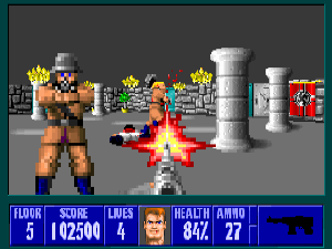
so as to accelerate much more the development of the 3D games scene, which by then was beginning to take off and which certainly represented the future in gaming:
Even the company’s engineers were fully aware of this, who candidly stated in an interview that they were aware of it already a year or two before the launch of this console, although the only thing they were able to conceive and implement to help the system was the packed/chunky to planar conversion logic that was built into the infamous Akiko chip, as we have already covered at length in some of the previous articles.
The idea is quite trivial both in terms of operation & use and implementation in hardware: four 32-bit registers are added to the new 32-bit address space we discussed above, which will contain the coordinates (16 bits each, for x and y) of the four points delimiting the trapezoid, and another 32-bit register which stores the length, in bytes, of a texture row to be used (which is associated with the B-channel DMA, as we saw earlier). It should be noted that the first point is also the one that coincides with the first value of the first line of the texture to be used, and so on for all the other points and then the other lines.
The Blitter will take care of setting up some internal registers, starting with this information, when this operation is selected (instead of line mode) and started, leaving the CPU completely free to continue with the execution of other instructions. Therein lies the most significant difference from how the coprocessor is set up when there is a line to be drawn, since for such operations the processor takes care of doing some preliminary calculations and then setting the registers appropriately, so that the blitter can immediately start with the operation.
Here, however, the aim is exactly the opposite: the processor is the weakest element of the system, computationally speaking, and we must try to make it carry out calculations as little as possible. So the coprocessor, at start-up, will carry out these preliminary calculations (which are, moreover, simple: it is a matter of setting the values for Bresenham’s algorithm for drawing the lines, but for the three most important lines that delimit the trapezium and serve to “direct” the operations), and then start with the real work.
Which is merely an automation of what we have seen before with rotation and zoom. To be clearer, the basic concept is to start from the first point on the largest side of the trapezoid (look at the figure above, “Quad”, for visual reference), and draw a line from that point to the corresponding point on the opposite side (via the adjacent line connecting them, of course: this is the line that must be drawn!), using the bytes of the texture to trace the various points as we go along. In this it is exactly identical to what has already been presented.
The difference lies in passing “automatically” (without involving the CPU) to the next point on that line, and for this we again use the pre-calculated values (again exploiting Bresenham’s algorithm), so as to find the next initial point of the larger side and the corresponding point of the smaller side (which could also coincide with the previous one: it is normal for there to be pixels overwritten several times, when we are talking about 3D graphics), as well as adjusting the texture pointer (which could move to the next line or remain on the current one). And so on for all points on the larger side, until the operation is completed.
Elementary solution (here the operation has been deliberately simplified, showing only one scenario, for a purely didactic matter, but the other scenarios are similar and follow the operation of the line tracing algorithm implementation in the Blitter. All that is needed is a little internal tweaking, in short), which is easy to use, not at all complicated to implement, and which also requires few resources for the purpose. But, above all, it would have made a huge difference in purely performance terms for realising 3D games.
Conclusions
This concludes this long article (sorry, but there was a lot of stuff to discuss and, in particular, to expound on here as well), which is focused on the description of the operation and implementation of the new 32-bit platform that could have been realised.
It might seem that there is too much meat on the fire, but in fact much of it has already been detailed and realised with the last version of the 16-bit (and 14MHz) chipset presented in the previous article, of which this 32-bit version represents an ideal completion (let’s say it completed the basis for future chipset advancements).
In addition, and in the meantime, Commodore’s production process has gone from 2 to 1.5um, thus enabling them to pack 2 / 1.5 = 1.33 = 33% more transistors for the same area occupied by the chips, allowing them to accommodate mainly the expansion of colour palettes from 16 to 32 bits. All this, in any case, should be taken with a pinch of salt because it is possible that the MOSFET process used by Commodore may have presented scalability problems.
Some may wonder why the whole system continues to run at 14Mhz and not 28Mhz, for example, since it would have been possible to raise the frequencies as well, two years after the previous one. The answer is that Commodore had to take into account its target market, which is the low cost/mainstream market, so it could not overdo it. In addition, continuing to rely on its MOS foundries was a big problem in terms of scalability (also in frequency), which in fact forced it to turn to HP for the implementation of the AGA’s most complicated chip (Lisa: the video controller).
The next article will bring the series to the end with the definition of the next possible 32/64-bit platform, also coming to conclusions.