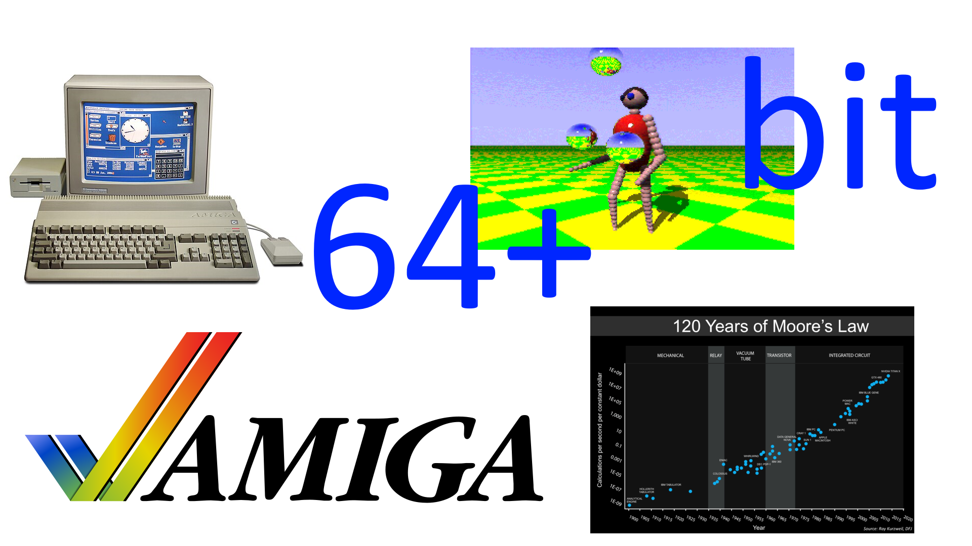
Having defined the foundations for the 32-bit incarnation of the new platform, one can also think about how the Amiga could have evolved taking into account higher capacity data buses, new types of memory (VRAM, in particular), higher frequencies, more advanced functionalities and optimisation of the existing ones (which are now feeling the weight of years).
On the other hand, competition from PCs has now become overwhelming in the round on the one hand, and consoles have heavily undermined our beloved “home” computers on the other, so answers were absolutely necessary, and of a certain calibre too, in order to remain competitive.
Commodore had what can be considered a virtue and a flaw at the same time: computers cheaper than the former for serious work, but also more expensive than the latter for pure entertainment. In medio stat virtus, the ancient Latins used to say, and that is why, despite the difficulties, the Amiga was still able to carve out a slice of the market that, among other things, could also count on a loyal user base (which still endures today!). Users who, therefore, waited for new releases, and for whom it was right and proper to invest in order to satisfy them (and make the company’s balance sheet happy as well).
1994: the time of Amiga 5000 (?), 1300(?), and CD64
Two years after the introduction of the 32-bit chipset, and with the foray of CD32 and the related automation of quadrilateral tracing (also useful for 3D) in between, it would have made sense to think about the introduction of the following improvements to the platform:
- 28Mhz chip frequencies for low-end/mainstream machines (home computers, consoles) and 56Mhz for mid/high-end machines (professional computers and workstations);
- 64-bit data bus for consoles and mid/high-end machines;
- screens from 640×480 (progressive/non-interlaced) at 32 bits up to 1280×1024 at 8 bits for low-end machines, and from 1280×1024 at 32 bits up to 2560×2048 (theoretical: having adequate monitors available) at 8 bits for high-end ones;
- Dual Playfield mode with two screens from 320×200 at 32 bits up to 800×600 at 8 + 8 bits for low-end machines, and from 640×480 at 32 bits up to 1600×1200 at 8 + 8 bits for high-end ones;
- Blitter with support for certain operations (minimum, maximum, sorting, addition and subtraction with saturation, blending, etc.) on packed/chunky data;
- flat shading and Gouraud shading for quadrilaterals and clipping;
- font drawing support;
- optimised pipeline of Blitter operations to improve performance;
- 15/16-bit (32/65 thousand colours) and 24/32-bit (16 million colours) sprites with resolutions greater than 16 horizontal pixels;
- ADPCM compressed samples for audio channels;
- 64 and 128 audio channels for the 28Mhz and 56Mhz machines, respectively;
- up to 16MB of Chip memory addressable by the chipset.
Commodore’s intentions for the AAA chipset were to release two versions in order to cover the low-end/mainstream and high-end markets, but in reality, and while still having two chipsets, it would have been possible to cover more market segments in a more granular and, above all, effective manner (more detailed offerings allow not only better coverage of markets, but the creation of new ones).
This is the reason why I proposed the 28Mhz and 56Mhz versions: the former allows the use of cheaper components (especially DRAM memories), to keep costs very low, while the latter allows much more, but obviously having to pay the price. In between are introduced both the possibility of using DRAM or VRAM memories, and the possibility of having the 32- or 64-bit data bus, which add variety to the offer. The latter is convenient for providing a little more computing power for possible consoles (such as the infamous CD64, based on the brand new Hombre chipset), without necessarily having to use expensive memories operating at very high frequencies.
As usual, part of the advantages (performance first and foremost, but also higher-resolution screens and sprites with more colours) derive directly from the use of higher frequencies and possibly also from the twice the size of the data “bus” (which also benefits devices, such as Copper for example, which do not use it directly, but which can exploit it to fill the internal buffers and thus access memory less times). There are, however, new functionalities that enrich and enhance the platform, besides the fact that these factors (frequencies and bus) can open the door to improving the existing one.
More colourful and/or wider sprites…
An example, in the latter case, is that of sprites, for which a double the size of the bus allows more data to be loaded and, therefore, the colours to be expanded by switching to packed/chunky 15/16-bit formats (32/65 thousand colours). Or by doubling its width from the canonical 16 horizontal pixels to 32 or more, with the same number of colours displayed, which can be useful when dealing with higher resolution screens.
Below are the changes to the registry that deals with this functionality:
| Bit 0 | Attach control bit (odd sprites) or packed mode |
| Bit 1 | Which of the two 256 colours palettes should be used or packed mode |
| Bits 7 – 2 | Palette portion to be used for 4 colours sprites |
| Bits 7 – 4 | Palette portion to be used for 16 colours sprites. Bits 3-2 should be zero. |
| Bits | Palette portion to be used for 256 colours sprites. Not used: bits 7-2 should be zero. |
| Bits 9 – 8 | Granularity for horizontal position (e.g.: sprites can be moved 1/4th of pixel in lores and 1/2nd of pixel in hires) |
| Bit 10 | Pure data: no control words are fetched for the sprites to set their start/end positions and additional data. So, only graphics data is fetched. |
| Bits 12 – 11 | Horizontal resolution |
| Bits 15-13 | RESERVED. Should be zero! |
| Bits 30 – 16 | Vertical position |
| Bit 31 | Packed/chunky mode |
The last bit, bit 31, signals the use of packed/chunky graphics instead of planar graphics. When enabled (at 1), it changes the meaning of the first two bits (which would be meaningless here anyway), like this:
- 00 -> 15 bits + 1 bit of transparency
- 01 -> 16 bit (colour 0 is used for transparency)
- 10 -> 24 bit (colour 0 is used for transparency)
- 11 -> 32 bit (alpha channel is used for transparency)
While bits 11 and 12 now allow the width to be specified:
- 00 -> 16 pixels
- 01 -> 32 pixels
- 10 -> 64 pixels
- 11 -> 128 pixels
As we can see, however, the number of sprites has not changed from the previous 32-bit and 14Mhz incarnation, while we have seen that the increase in frequency has led to a proportional increase in their number, reaching a total of 32. It would therefore have been logical as well as natural to think that, being able to count on frequencies of 28 and 56Mhz, their quantity would have reached 64 and 128 graphic objects respectively, which would have been able to run across the screen.
There are, however, two reasons why I preferred not to do this, leaving their number intact. The first is that adding sprites entails greater complexity of the video circuitry, which would either affect the achievable frequencies/resolutions, or introduce latencies in the signal display. The second, which I personally find more important, is that the entire industry was by then moving towards 3D (the first console, the 3DO, was marketed in ’93: right after the CD32!), so there was no point in further burdening the platform to add objects that would be substantially useless in the future.
Much better, therefore, to take advantage of the new slots (Chip memory access possibilities, in amighist jargon) to double or quadruple those available for the existing sprites, allowing them to load more graphics and, therefore, to be able to decide to display more colours (up to 32 bits = 16 million, with alpha channel attached if necessary) or to enlarge them (to 32 or more pixels wide). Both possibilities would certainly have been useful in enriching the gaming experience.
… and more audio & ADPCM channels
The opposite is true for the audio channels, for which it is much better to use the increase in frequencies to increase their number by two (64) and four (128) times, respectively, since the trend is to have more and more audio sources to associate with the objects or characters that populate video game scenes (the soundtrack, on the other hand, has become the prerogative of the CD-ROM on which games are often carried).
The audio subsystem had already been rethought with the 16-bit / 14Mhz chipset to accommodate these challenges, so the implementation of the new channels is neither complicated nor onerous, requiring only slightly more precise DACs, as well as adders (which perform the mixing) that are equally more accurate in their calculations.
There is, however, one difference: the new 32-bit registers reserved for audio channels (which were presented in the previous article) were exhausted, because there was only room for 32 of them in the 512 bytes available. Therefore, another way is needed to map them, and in this case there are two possible solutions (or… both).
The first is to use the same technique of subdividing the channels into banks (in this case of 32 channels at a time), similar to what is proposed with the 16-bit / 14Mhz extension, and which more or less replicates what is implemented in the AGA chipset for colours management (only 32 colours of the 256 in total are mapped at any one time). This also allows the additional registers (AUDCON0, AUDCON1, AUDDMA, AUDINT, AUDREQ) which have been presented and which serve for the management of these channels (going beyond the 4 defined by the original chip) to be quickly resolved.
The second solution is to reserve a new memory area capable of housing all these registers (and also ready for subsequent expansion). The problem is that the memory area reserved for custom chips has already been completely used up ($DFF000..$DFFFFF). So another one should be used, such as $DF8000..$DF8FFF, which allows as many as 256 channels to be mapped (and which could also be extended further in the future).
The only snag is that Copper wouldn’t be able to access it (since it can only do so with the current registers), but that wouldn’t be a major limitation (unless you want to use this coprocessor itself to programme audio channels to play soundtracks and sound effects, as I did with USA Racing, the game I was working on). At the limit, you could also implement both solutions, so that you have complete freedom in deciding how to access these registers.
Finally, ADPCM encoding: as the number of channels increases and, therefore, also the number of usable samples (also 16-bit), as well as the operating frequencies (up to 56kHz, as we know), space begins to become tight, so this solution helps in this sense, allowing the samples to be compressed with an acceptable quality. Which is not particularly onerous, if we consider that the Super Nintendo had already implemented it in 1990.
In this case, the audio control register is slightly modified, using one of the previously unused bits:
| Bits 1 – 0 | Samples size: 0 -> 8-bit, 1 -> 16-bit, 2 & 3 -> RESERVED |
| Bit 2 | One shot: only reproduce the samples one time and then stops |
| Bit 3 | Sample from external source |
| Bit 4 | ADPCM |
| Bits 15 – 5 | RESERVED |
| Bits 31 – 16 | Period (number of color clocks) |
The Blitter begin to “do the maths”… even with 3D!
With the definitive clearance of packed/chunky graphics (in this period there is no longer any point in using planar graphics, with their relative chromatic poverty: it’s time to let the pupils rejoice!), it is possible to think of introducing some primitives applicable to the jobs taken over by the Blitter, to help with some fairly common tasks and thus lift the burden from the CPU.
Something that even the last chipset being worked on by Commodore, the AAA, had foreseen, and which is not surprising, since it is a natural evolution as well as inexpensive in terms of implementation. If operations such as minimum, maximum and sorting (and others) may not sound so relevant to graphics (they are by far more useful for more “general-purpose” processing), addition and subtraction with saturation and the various blending modes, on the other hand, allow various effects to be implemented quickly and effectively:

The need to better support 3D processing also became extremely important, given that the gaming market was strongly moving in that direction, and the “32-bit generation” of consoles was now represented by models whose main hardware support was reserved for this type of calculation, so much so that some consoles did not even offer 2D support.
It was therefore imperative to expand the scope of the chipset modifications, which had already begun with the 32-bit version, and further optimised with the home console (the CD32), by implementing so-called shading technologies in hardware for the polygons to be rendered.
In particular, flat shading is very affordable and easy to implement:

which, as can be seen, consists of dealing with a single light source applied to each individual polygon.
The effect is not bad and represents a huge step forward compared to textures applied as is, without any lighting, but a much better solution is achieved with Gouraud shading:
The difference is remarkable, as can best be seen here:

In order to support the latter type of shading, it will be necessary to introduce four new 32-bit registers in the Blitter, in which it is possible to specify the colours at the four vertices of the quadrilateral to be drawn, and which will be interpolated during its drawing to generate the colour of each pixel. In the case of flat shading, however, it will be sufficient to use only the first colour (it will be the only one interpolated with those of the pixels of the quadrilateral).
Another important addition regarding 3D graphics is that of clipping. As we have seen in the previous article, the ability to plot quadrilaterals entirely in hardware involved the introduction of four registers for the coordinates of the four vertex points, but the actual operation can encroach beyond the size of the screen, as there is no control over this.
For this reason, two additional 32-bit registers can be added, containing the coordinates of the rectangle in which to limit the quadrilateral tracking. In addition to avoiding the problems already mentioned, this feature is very useful because in this way the Blitter can automatically skip the rendering of the parts that are not to be traced, thus speeding up the operation considerably.
A new pipeline for the Blitter
All these modifications would have contributed a lot to the acceleration of 3D graphics tracing (compared to what was available with the original chipset, of course), reaching a theoretical limit of about 7.16Mpixel/s in the 56Mhz version, which comes substantially with the passage from 7Mhz (and almost 0.9Mpixel/s) to this new frequency (eight times higher).
Sufficient to cover the rendering requirements of a 320×240 screen at 60Hz/FPS (which requires the tracing of about 4.6Mpixel/s), but still assuming that each pixel of the screen is rendered only once. This scenario is not very realistic, as in 3D it is much easier for a pixel to be overwritten more than once. So it is obvious that much more “firepower” is needed to maintain good frame rate.
On the other hand, one only has to look at what the competition has to offer. The aforementioned 3DO, marketed in ’93, is capable of tracing 9-16Mpixels/s. For Sony’s more famous Playstation, which arrived a year later, only 360,000 polygons per second in flat shading, 180,000 with texture mapping, and 90,000 with Gouraud shading are reported, so direct comparisons are not possible, although they are quite large numbers and therefore suggest very high levels for Mpixels/s.
The approximately 7MPixels/s that can be achieved at such high frequencies (56Mhz) appear, therefore, to be very little, and the reason for this lies essentially in the fact that it is all based on the operation of the Blitter, which in order to draw a single pixel with Bresenham’s algorithm for lines is always based on a sequence of four slots (memory accesses), which equate to 8 clock cycles (hence the value in MPixels).
It all made perfect sense and, indeed, was absolutely necessary as long as it involved planar graphics, but a pipeline operating in this way:
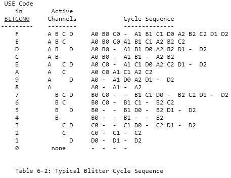
even with packed/chunky graphics represents an enormous limitation that severely clips the wings of performance, as we have seen. What is urgently needed, therefore, is not so much a redesign when graphics are in this format (so as to eliminate these bottlenecks and finally give the green light to performance), but a new ad hoc pipeline (leaving the original one intact to continue handling planar graphics as usual).
Packed/chunky graphics, in fact, do not require the classic shifting / masking / insertion operations that are needed when dealing with planar graphics (where a pixel represents a bit in memory, which is clearly not directly addressable), which also requires reading the screen graphics for this very reason.
This is not necessary, because the individual pixels are nothing more than bytes, words (16 bits) or longwords (32 bits) that can be directly read from or written to memory. That is why you do not need four slots (equal to eight clock cycles) to be able to plot a pixel in this format, but only half: one slot to read the pixel colour from the texture, and another to write the pixel generated for the quadrilateral. On balance, performance would double to 14.32MPixel/s: a respectable value and in line with that of 3DO.
Some further optimisation would be possible in the following cases:
- avoiding reading the texture if the colour to be used is the same or is part of the block already read (remember that when accessing memory, as many as 16 bytes are read at a time in a system with a 64-bit bus and fast page memory mode);
- collecting the adiancent colours (same line, in sequence) generated for the quadrilateral and which should be written in memory, but which one could avoid writing immediately and store them internally until the new pixel to be written would be part of a different memory area, or if we have reached the end of the line to be rendered.
It is not possible to make estimates of the gains, because it obviously depends on the various cases, but I think that the implementation of these two optimisations would significantly raise the value of the approximately 14MPixel/s.
A hybrid scenario: drawing fonts
A very useful extension of the new pipeline and, in general, of the way quadrilaterals are drawn, is to be able to draw fonts to write text. A very common and indispensable operation, but rather slow with planar graphics and, above all, entirely CPU-intensive with packed/chunky graphics.
In this case, it is necessary to use one of the channels of the Blitter, in this case the first (A), to load the monochrome graphic (a bitplane!) representing the shapre of the characters, which will shift one bit/pixel at a time and which will indicate whether one is in the presence of a character pixel (which, therefore, must be drawn) or not (the screen must not be modified).
Everything else works in the same way, as the character graphic can be likened to a quadrilateral to be drawn on the screen, so it will be possible to rotate and zoom it as we also saw in the previous article.
With packed/chunky graphics, however, we must also introduce the way in which the pixels are to be drawn, and specifically:
- with only one colour (it will be the first of the four previously defined for Gouraud shading);
- with two colours (in this case there will be no transparency: pixels not belonging to the character will be drawn, but with the second colour);
- with a texture associated with the B channel (so it is possible to design fonts with very varied patterns, such as marble, fire, etc., without having a copy for each type, as was the case with Kara Colorfonts, if anyone remembers them).
Conclusions
This last feature also brings this series to a close. It should be noted that nowhere are figures given on the possible use of VRAM memory. The reason for this is that the use of this type of memory does not automatically lead to a doubling of performance, as one might think, but the resulting benefits depend on the particular scenario. Even some of the data provided with the AAA documentation does not show strictly linear increases, but the results are variable. The only thing that is certain is that there would have been substantial advantages in using this memory (otherwise they would not have been used!), so numbers and speculation are absent.
Apart from this necessary clarification, there were so many shortcomings of our beloved platform, as we have amply seen, as well as so many opportunities to improve them, which were wasted not only due to the short-sightedness and ineptitude of the management, but also of the technical department, which, with the departure of the original group, showed an inability to act and decide in which direction to go, among other things, passing the blame for the failures entirely on to the management and washing their hands of it.
Those who remained, on the other hand, were not up to the task and showed inadequate capabilities, as was revealed in interviews and stories that were collected and published in books. An example of how inadequate they were is provided by the chief engineer, Lew Eggebrecht, whose assessment in one of these books is merciless to say the least:
He (Eggebrecht, ndr) was also somewhat critical of Commodore’s hardware and software engineers, feeling they were “hardware hackers” and unprofessional…
He calls them “hackers” and unprofessional, and with very good reason I would say. We have seen, in fact, how they are accustomed to placing a few ugly patches to solve a certain problem, instead of thinking and implementing better, more elegant, and future-oriented solutions.
Unfortunately, the past cannot be changed, and we hold on to what we have been able to enjoy, even if the mind sometimes dwells on what could have been done, because it is still not resigned to the idea of the enormous advantage the Amiga started with and the immense capital that was squandered due to everyone’s incompetence.
List of previous articles in the series
Missed opportunities to improve the Amiga chipset – 1: audio
Missed opportunities to improve the Amiga chipset – 2: graphics
Missed opportunities to improve the Amiga chipset – 3: frequencies
Missed opportunities to improve the Amiga chipset – 4: memory data width
Missed opportunities to improve the Amiga chipset – 5: Commodore’s innovations
Missed opportunities to improve the Amiga chipset – 6: the alternative of 16-bit innovations
Missed opportunities to improve the Amiga chipset – 7: the alternative of 32-bit innovations