We have seen how increasing frequencies could have made it possible to considerably improve some very important aspects of the Amiga chipset, remedying (and even overturning!) some major limitations of its architecture which, unfortunately, greatly reduced its potential.
Having higher frequencies is one of the banal solutions (at first glance) when talking about improving electronic components, as is another equally “obvious” one that allows one to act on another front: that of increasing the size of data read from or written to memory (clearly with equal access time).
Both of these are trivial because, precisely, anyone is capable of making “high-flying” proposals: it is the simplest and most natural thing one can conceive of. The question, however, remains that of contextualising (evaluating according also to the technological limitations of the time) and verifying their actual effectiveness as well as their applicability to the specific problem to be solved.
Apart from that, and as also emerged in the previous article, we also need to see whether increasing something can open more or less hidden little doors (or perhaps gates) in some area, taking advantage of the peculiarities of the specific system. And this, for me at least, remains the most interesting and “nifty” part.
Going beyond 16 bits
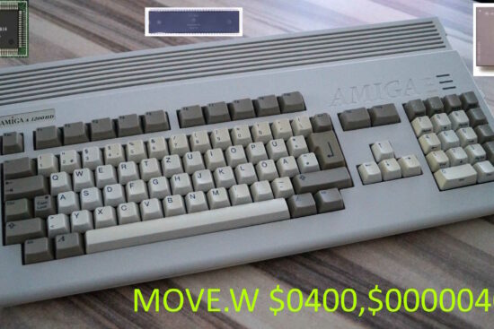
The Amiga, as we know, was for a long time considered a 16-bit platform. Unfairly so, since the architecture is 32-bit. Having, however, the 16-bit data bus (both for the Motorola 68000 processor and for the chipset), it took it as a trademark, and that is also why it is considered a 16-bit system (even in gaming: “16-bit generation”).
The opportunity to switch to (“full”) 32-bit could have been the Amiga 3000, which sporting a Motorola 68030 CPU would have made the remarkable step forward. Unfortunately thwarted not only by the chipset (ECS) which remained 16-bit (such is the size of its bus for memory access or by the processor), but even by the Chip memory.
In fact, this is the only one that the three custom chips can access and which, despite being 32-bit (only for the CPU), forces the processor to spend four clock cycles to be able to read or write to it, even though it can only do so in a couple of cycles.
The reason is that the chipset continues to operate as if it were serving the 68000 processor (which, just to simplify, accesses memory every four clock cycles), thus forcing any processor to operate in this way, effectively halving the possible accesses and, consequently, the total bandwidth.
As if this were not enough, custom chips remained with a 16-bit bus to access their registers even if the CPU has a 32-bit bus, thus requiring twice as much time each time. More details on both these aspects can be found in this thread on the most famous Amiga portal.
Once again we have to “thank” Commodore’s engineers for “goodies” like this, which castrated the evolution of the platform even when there was really no need.
A limitation that incredibly remained even with the next chipset (coherent people, the engineers), the AGA, even though the data bus was finally upgraded to 32 bits for this one as well. Indeed, they even took advantage of the memory’s fast page mode to be able to read two 32-bit data bits (so 64 bits in total. In this case, the data must be aligned to 64 bits, i.e. be on the same memory “page”).
As a matter of fact, the memory bandwidth (amount of data that can be read or written in the unit of time) has basically quadrupled, although this prodigy was reserved exclusively for the video controller (for displaying screen graphics) or sprites, while all other devices (disk, audio, Copper and Blitter) remained completely dry (in fact, they never received any changes in the entire life of our beloved platform).
Double (and quadruple) speed disc
One of the Amiga’s gripes was that software was carried almost exclusively on floppy disk, but at double the density (880kB on the Amiga, in its standard format. Custom formats allowed more data to be packed) and quite slow (it took just over 35 seconds to read the entire contents of a disk).
PCs and Macs, on the other hand, quickly adopted high (1.44MB) and even “extended” (2.88MB) density disks, which for the same amount of read and write time allowed much more data to be transferred (effectively halving or reaching 1/4 the time for the same amount of data).
High-density disks also arrived on the Amiga, but due to the limited number of memory accesses reserved for the disk’s DMA, they had to be read at the same speed as double-density disks, thus requiring twice as much time (and special drives: you couldn’t use those of PCs; moreover, they were cheaper).
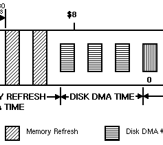
In fact, and as we have seen in previous articles, only three odd slots were reserved for the disk for memory access:
Even slots could have been used to double the number, which I did not propose in the other articles (although technically feasible) for a couple of reasons. The first is that it would not have allowed extended density disks to be supported (which would have required a further doubling of all slots).
The second is that, again related to the latter case, this would have required the creation of an additional register to specify the length of the buffer to be used to read or write data from the disk.
In fact, the disk uses a 16-bit register for this purpose, DSKLEN, which allows buffer lengths of up to 16383 words (two bytes) to be specified, which is enough to hold an entire track of a double-density or high, but not extended, disk.
Finally, but this is my very personal opinion, it would have been preferable to exploit the slots to increase the number of audio channels, as I have already illustrated, because they were objectively more useful due to the platform’s poor polyphony (only 4 channels, when the competition had already made many more available).
Much better, therefore, to wait until we can have access to memory with larger data (32 and 64 bits) in order to be able to also extend the disk operation and support high and extended density disks. First, however, we need to understand how the disk controller actually works and how it uses the three available slots (also because it will also be useful with proposals for improving other devices).
When it comes to the allocation of DMA to access memory by the various devices, the most important concept to understand is that these slots only represent an opportunity for them, which they can decide to take or not (thus leaving them free to be used by Copper, Blitter, or CPU).
Specifically, if the disk controller has something to read or write, then it can use its three slots for the purpose, or even just some of them, depending on how long (in terms of words = two bytes) the buffer it will use for the purpose (to read to write to disk, and vice versa to write to data that has been read from disk).
If, for example, it needs to write data to the disk, then it will use up to three to read the data that is left in the buffer, storing it internally for when the individual bits actually need to be transferred to the magnetic head to actually complete the operation.
When, on the other hand, it is reading data from the disk, it will store it internally until it has up to three words ready to write into the buffer that it will need to use.
It should be emphasised that the disk controller is forced to use an internal buffer, as the data read from the disk or to be written to the disk is read or written “always” as the head is at a particular position on the disk. This means that it has no freedom to choose when to access memory to access its buffer, so it can and should only do so in the three slots allocated to it.
And it is precisely the concept of the internal buffer that is fundamental for understanding how the possibility of reading/writing 32 or 64 bits of data from/in memory in one go (as the AGA does) could have been best exploited, extending it to all devices in a simple and non-invasive manner (as we shall see later).
In the case of the disk, the solution would be simple and transparent, because there are two sensors (connected to lines in the cable that connects the computer to the drive) that determine whether the inserted disk is normal, high, or extended density. For the s.o., it is sufficient to read its status to adjust accordingly the size of the buffer to be used and how many words (two bytes) are to be read or written, also taking care to align the buffer to 32 or 64 bits (as the case may be).
The disk controller (to which the data from the two sensors will have to be sent so that it too is taken into account) will in turn have to have its internal buffer doubled (to read and write 32 bits at a time, for high density disks) or quadrupled (to read and write 64 bits at a time for extended density disks).
So instead of 3 words (2 x 3 = 6 bytes), it will have to have 3 longwords (4 x 3 = 12 bytes) or 3 quadwords (8 x 3 = 24 bytes) depending on the maximum size of the “bus” to the memory (I put this in inverted commas to indicate that it is not really about the bus, but the ability to access data even larger than the bus itself, as is done with the aforementioned fast page mode).
The DSKLEN register will also automatically change accordingly: if the sensor detects a high-density disk, then it will not contain the number of words to be read or written, but the number of longwords. Whereas it will indicate the number of quadwords if the extended density sensor is active.
At this point, the game is over: with only three slots available, it would be possible to support high and extended density disks, with minimal changes and, above all, at full speed.
Audio channels with higher frequencies and 16-bit samples
Similar reasoning could have been done with the audio channels, as they too use internal buffers to store the samples to be played from their associated buffer.
As there is only one slot for each individual channel:
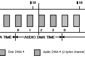
only one word can be read from memory, which contains two 8-bit samples to be played (the Amiga’s audio is 8-bit, as we know). Internally, the audio controller will use the first sample, and switch to the second when it is needed (i.e. when the playback period of the first has “expired”).
Reading 32 or 64 bits from memory would have supported higher frequencies than the 28khz maximum normally allowed by the single 16-bit slot, doubling (with 32 bits) or quadrupling (64 bits) the size of the internal buffer.
In this way it would have been possible to reach playback frequencies of 56 or 112khz, respectively, while still remaining with 8-bit samples. With the constraint, as already explained in the case of the disc, of having the buffer aligned to 32 or 64 bits.
All this would have been done transparently, as no changes would have been needed to the internal registers, nor to the way the OS and developers program the audio channels, apart from the due care of aligning the buffer to the respective size of the data “bus”.
A very small modification would have been necessary, however, to support the coveted (and dreamed of!) 16-bit samples, as it is necessary to indicate to the audio controller their presence, so that it can adjust accordingly on how to treat the data in the internal buffer and, of course, how to send them to the DAC (which would obviously have to be switched from 8 to 16 bits) for their conversion into a real sound signal.
In this case bit #7 of the AUDxVOL registers associated with each individual audio channel is free and can be safely reserved for the purpose. Bit #15 is also free, and combined with #7 would allow the audio to evolve further in the future, to support different samples (32-bit and fp32, for example).
Enabling 16-bit samples would, however, also lower the maximum supported frequencies to 14, 28 and 56khz for data “bus” sizes of 16, 32 and 64 bits respectively. But I think these are largely digestible limits, in order to be able to take advantage of this new (and highly anticipated, in the 1990s) functionality.
It should also be stressed here that the modifications required, apart from being minimal (except for the 16-bit DAC, obviously), are totally backwards compatible with all the software already existing for the Amiga (and which has faithfully followed the parent company’s guidelines. Which is far from obvious, unfortunately).
Copper on steroids puts the pedal to the metal
All devices with fixed / predetermined DMA allocation slots have been covered, but the concept of using internal buffers to store more data from the “expanded” memory bus could also have been applied to the Copper, which instead simply reads its instruction data… when it can, and executes it as soon as it has all their bits (32) available.
In fact, it too makes use of an internal buffer, being forced to wait until it has read the two words (with the 16-bit bus) of the next instruction, and only then, finally, proceed to its execution.
Extending the “bus” to 32 and 64 bits could also increase its internal buffer accordingly, taking it from one word (the one previously read) to a longword (32 bits) or quadword (64 bits), depending on the size of the “bus”, but taking care to add an internal counter that signals the total number of words that are still available (after the just executed instruction).
Copper’s behaviour should change slightly at this point. In fact, when it is ready to execute the next instruction and there are at least two words in the internal buffer then it can use them to execute that instruction immediately, then remove them from the buffer (moving any remaining words to the beginning, and updating the internal counter).
One immediate advantage of this simple solution is that the Copper will consume half (with a 32-bit data “bus”) of memory bandwidth, or a quarter (with a 64-bit “bus”), thus leaving several slots free for use by the Blitter or CPU.
Another is that it would be at least twice as fast if the instructions in memory were aligned to at least 32 bits (as it should already be natural to do anyway), because that way when it goes to read from memory it will immediately find itself with the 32 bits it needs for its instruction, without having to wait for the next free slot to load the second part to complete the instruction.
Actually, with the 64-bit “bus” it could go even faster, considering that in one go it could load as many as two instructions at a time (always taking into account that the buffer should be aligned to 64 bits).
In this case, it could execute the second instruction immediately after the first one, thus in the next system clock cycle. Remember, in fact, that one memory access slot is equivalent to two clock cycles, so the second instruction could also be executed in the first subsequent system clock cycle (the first “half” of the following slot). All this while the DMA prepares to read the next memory data (another 64 bits).
Such a fast Copper would make it possible to perform many more visual effects: first and foremost, changing the colour palette (a fairly common operation), but sprite multiplexing would also benefit enormously. If we then add to this the loading of several registers with a single instruction (a modification suggested in a previous article), the apotheosis would be reached…
Similarly, the previous proposal of a stand-alone DMA channel to directly load the registers of the three chips (primarily for colours; as usual) would also benefit enormously from being able to read 32 or 64 bits at a time instead of the canonical 16, halving or requiring 1/4 the time.
These marvels, however, could not and should not be made available immediately, because full compatibility with the software already written, which expects Copper to behave very precisely, would be lost.
The solution to this problem is the same as that presented in the article that proposed the introduction of loading more than one register at a time via the Copper’s MOVE instruction: it must be enabled on purpose, using the same bit. So if you enable the new MOVE you will at the same time enable the use of the extended 32- or 64-bit buffer and, consequently, faster instruction execution.
Blitter wastes much less bandwidth (and is perhaps even much faster)
The Blitter, too, could have benefited from some improvements arising from the possibility of accessing larger data in memory at the same time, although perhaps (this is only a hypothesis) not being able to reap the same advantages in purely performance terms (as we shall analyse later).
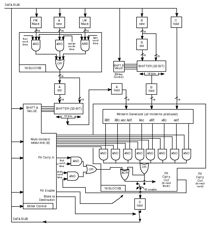
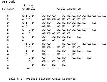
In fact, it too makes use of some internal buffers in which it stores, and then uses when it needs it, the data read from memory by the three DMA channels it has available (called A, B and C), and finally writes the result of their processing into memory using a further channel (D):
The existing buffers (for channels A and B. For C, one can be added) can, therefore, be extended in a similar way to that seen for the Copper, in order to store the words (two bytes) read from memory and their quantity. In fact, even if it is possible to read 32-bit (2 words) or 64-bit (4 words) data, it will not be possible to use all the words, because the channels and the Blitter always work on single words at a time, and some of those read may be useless for the operations that this coprocessor has to perform.
For example, if channel A points to memory location $01DED2 and the bus reads 64 bits from that memory area, it will do so using $01DED0 as the address (because 64-bit data must always be aligned to addresses multiple of 8, so the first 3 bits of the address are discarded, and $01DED0 is used).
Since the data needed for channel A starts at $01DED2, it means that of the 4 words being read, the first one will be discarded (because it is at $01DED0), while the following three will be retained internally because they are or could be useful later.
Therefore, and although 64 bits can always be read, it will not always be possible to exploit all four words read. The potential is there, but to be exploited to the full, the data must always be aligned to the size of the data “bus”. This is not always possible, but very often one could take advantage of it (it is the average case that is important here; not the worst case).
The advantage would lie in the fact that if, for example, a channel were to work with three words that were located one after the other in memory, and exploiting the 64-bit “bus” those three words would be read all at once, then the Blitter would not need to perform three separate accesses to retrieve them, but only one.
Thus saving a considerable amount of memory bandwidth and leaving the other two slots free for the CPU, for example, which could then have many more opportunities to work in parallel with the Blitter, sharing the work in some cases.
Theoretically, this should not be the only gain from using larger internal buffers to accommodate the data the Blitter will need in the future, as having them already available it could continue processing “immediately” without having to wait to read them.
To clarify this, it is necessary to understand how the Blitter works. For example, when it has to use all three channels for a complex operation (and very common in games or in the design of user interface graphics), it must first read the data from all three from memory, and only then it can use them for processing, producing the data to be written (again in memory).
So its execution speed would be substantially limited by waiting for the data it needs. But if the data were already available because it is contained in the internal buffers thanks to the “bus” that is wider than the canonical 16 bits, then in theory it could immediately start processing the next operation and send it to memory.
The conditional is a must, because everything depends on how this coprocessor is implemented internally, which is equipped with a pipeline to efficiently divide up all the internal operations it has to perform to reach the final result:
If there are no dependencies between the various stages of the pipeline (e.g. operations that have been specifically planned to be executed at a certain stage, taking into account the memory accesses that are always necessary), then one could apply what is technically called a “bypass” and thus “skip” the data read stage for that channel (or even for all of them, if their data is already present in the internal buffer) and go directly to the next stage concerned (the data read of the channel that has no data and must draw it from memory, or that of the actual calculation).
In this way the performance of the Blitter could be more than doubled, if we consider that with a 64-bit “bus” and in the best conditions (all channels are aligned at 64 bits) 4 words would be read for each channel, thus requiring 3 slots (equivalent to 6 clock cycles), and then requiring 4 slots (8 clock cycles) to write the 4 words of the result into memory.
Total: 14 clock cycles (and 3 + 4 = 7 memory access slots consumed), when to do the same with the 16-bit data bus would have required (roughly) 4 x 8 = 32 clock cycles (and 8 slots consumed).
At the slot level, one could still optimise something by using an internal buffer for the result words as well, getting to write 4 to memory (with a 64-bit “bus”) in one go under the best conditions (with the D channel aligned to 64 bits).
Nothing would change in terms of performance (because the Blitter always works internally one word at a time, producing one word as a result for each slot), but three precious slots would be saved that the CPU could exploit to its advantage.
All this, I reiterate, on the assumption that the pipeline stages of this coprocessor can be bypassed when the necessary data is already in the internal buffers. Otherwise, performance would always be the same, and the only possible saving would be that of the memory slots (which would in any case be very good for foraging the processor as well, which at this point would be able to do quite a few calculations independently, contributing substantially to the overall performance of the system).
Let’s exploit the free slots with… a second Blitter!
One way to exploit the slots left free by the Blitter without them ending up on the CPU (which, by the way, might not even exploit them if it is busy with internal calculations, so they would be wasted) would be to add a copy of it.
Then a second Blitter, either with its own bank of registers or sharing them transparently. Whatever the solution, I don’t want to dwell on the explanation, because it adds complications that the programmers have to manage (how to make the best use of them / keep them busy, and above all without them “stepping on each other’s toes” by working on the same memory areas).
Let’s be clear that it would certainly have been feasible and would have quietly consumed all the slots vacated by the first Blitter (as well as making the system overall about four times faster than the original), but it would have required quite a few transistors and, thus, a complexity beyond the scope of the minimal changes to the chipset that these articles have set out to achieve (at least so far).
Exploiting bigger data
In fact, making the most of the greater width of the “bus” in memory could certainly be done without resorting to such expedients: it would “suffice” (!) to extend the operation of the Blitter from single words (16 bits) to longwords (32-bit bus) or quadwords (64-bit “bus”), and possibly more, depending on the available interface to memory.
Thus, this coprocessor would always require 4 slots (equal to 8 clock cycles) to complete a single internal operation (three to read data from channels A, B and C. One to write the result via channel D. This in the most complex scenario), but at 32 or 64 bits (or more) instead of 16 bits, maximising the exploitation of memory access (and, by extension, performance: up to four times… or more).
In words it sounds easy, because there has always been much talk in the Amiga community of a phantom 32-bit Blitter to improve (double) performance, but such a thing has never appeared nor been revealed (except in the documentation of some chipsets in the works, such as the AA+ and AAA).
Some attempts seem to have been made with designs such as the Natami (which we have also talked about in these pages – in Italian), but from memory I recall that in some threads in their forum it was mentioned that the designers were not satisfied with the performance achieved.
However, the most important issue, in my opinion, is that all these attempts to expand this coprocessor to 32 bits would not have been viable and scalable solutions for the future. Just think, in fact, of the possibility of reading and writing 64 bits at a time: would a new 64-bit Blitter have been necessary? And when 128 bits would have arrived, again another one? And so on.
It is clear that this rather narrow-minded (and very uncreative!) mentality of redesigning a component every time, just because more data can be accessed, does not work: it represents the classic patch to be put on quickly to solve the contingent problem, without a vision for the future. Moreover, it places the entire burden on the programmers (who will have to adapt their code to the new component. Every time!).
The “agnostic” Blitter (not tied to the “bus”)
What is needed instead is a component that works and offers a consistent and automatically scalable interface for the future, with no further modifications other than purely internal ones to adapt to new memories.
It may sound absurd, but the Blitter does not need any modification to any of its registers, as its interface for programmers already offers all the necessary abstraction to handle any request in the best possible way, regardless of the size of the data “bus” to which it is connected.
The only modification required (and this also applies to the enlargement of the internal buffers discussed in the previous section) is a single bit in one of its control registers, which can specifically enable the new behaviour, so as to preserve compatibility with software already written and which expects strictly different operation (as shown in the above diagram of its pipeline).
Everything else is and must be handled internally, with this coprocessor having to adapt to the request it has received, taking into account the maximum size of the “bus” it is connected to and, therefore, how big the data it can (and must) manipulate.
This is far from clear, I realise, because up to now it is extremely difficult to understand how a device born and working on the strict basis of manipulating words (16 bits) can work quietly on data of a much larger size and manage (much better) the same, identical requests that come to it (I repeat: not a comma of how it is programmed must be modified, apart from the aforementioned bit to be enabled).
Since the issues are strictly technical and the article has already reached a considerable length, I will limit myself to illustrating the basic idea without making it too heavy, concentrating on a few concepts of fundamental importance.
The first is that while it is true that the Blitter works with single words at a time, it still does so over a rectangular area that it must process. To do this it divides its work into rows (all of equal size = number of words), and this is the first concept to dwell on.
In fact, the words are read as they are read, but this is only because it must process the entire row that is currently (when the task was started) being processed (we can ignore for the moment the fact that the work area is rectangular, because in the end it is always a matter of applying the same operations to each row).
This is because the words read are, very often, concatenated. The A and B channels of this coprocessor are capable of shifting (left or right, depending on how it is set, from 0 to 15 bits/pixel) the bits of these words, in order to align the graphics to the desired position (in pixels).
This can be seen in the internal diagram: A and B are the only ones that have this possibility, and work 32 bits at a time (making use of two consecutive read words). While channels C and D do not require any shift: their graphics are ready to be used or sent to memory, respectively.
To try and simplify, channels A and B are used for graphics that may be “misaligned” with respect to the horizontal position (in pixels) of the screen on which we want their graphics to be displayed. For this reason, they are given the possibility of shifting their data: to position them exactly where we want them.
Whereas the C channel does not need this, because it (generally) points precisely to the screen graphic that will be updated (in this case its current graphic is loaded, before the change). For the same reason, channel D does not need any shifting, as it will eventually contain the updated graphics (at the end of all processing with channels A, B and C).
Since this coprocessor always works with word (16 bits), this means that it must take the graphics from A and B, position them appropriately horizontally, extract/use only 16 bits (of the 32 bits read), combine them with those of C (16 bits), and finally store the result (16 bits) using D. The idea, therefore, is to be able to obtain 16 bits from these “adjustments”, so that they can be written to memory (which can only be read or written in word).
With a 64-bit “bus” the concept is exactly the same, only in this case we would need to specify shifting from 0 to 63 for the data coming from channels A and B. Furthermore, their graphics should always be aligned to 64 bits.
Only there is no room in the Blitter’s registers to add the necessary bits for the purpose, but in any case this solution would go against the reasoning set out above, where one would like its registers to remain exactly the same regardless of the size of the “bus” (on the other hand, with 128 bits one would have to add even more bits for the purpose, and so on with larger “buses”).
Moreover, this coprocessor is always given the number of words to work on for each line, so with each change in bus size, more bits would have to be added here too. It is clear that nothing like this could ever work, because it would not be scalable at all.
The solution to the problem: let’s exploit what we already have!
The solution I have found is to continue using the words as the basic unit for the operations of the Blitter, but exploiting the information present in the pointers (memory locations) to the data of all four channels of this device, so as to automatically and internally regulate all the shifting and masking operations.
I’ll give an example with channel A (which is the most complex, given that it also has two special registers associated with it to mask the first and last words that are read for each line to be processed), but the concept is also exactly the same for channel B (without the two masks) and for channels C and D (without any single-pixel shifting; but they must also be changed slightly).
Let us assume that channel A points to location $01DED4 for its data, that the Blitter has been asked to process a rectangular area with rows of 3 words, that the “bus” is 64-bit (so as many as 4 words can be read or written at a time), and that A’s data must undergo a 5-bit/pixel shift to the right.
Normally, with the 16-bit bus, channel A would need to read two words before it could use this data, because of the 5-bit shifting required. In fact, if only the first word were read and its 16 bits were shifted 5 places to the right, it would not be able to continue working because it would be missing another 5 bits.
It must, therefore, read two words, combine them (put them one after the other), and at this point it has (at least) 16 bits (it has 27, to be precise) that it can combine with the 16 bits coming from channels B and C, and get the 16 bits to send to D.
The same concept applies now that the bus is 64 bits. However, the aforementioned memory location is not 64-bit aligned. In fact it should have been $01DED0 or $01DED8. But the programmer is not aware of the size of the “bus”, so he has made its legitimate request without taking this into account, and the Blitter will still have to complete the operation.
In this case he will read all four words at the first address, but will have to discard the first two (because they are at addresses $01DED0 and $01DED2, while the A-channel starts at $01DED4), while retaining the fourth word (which is at address $01DED6) because it is part of the three words (per line) he was asked to process.
So it has read 2 words = 32 bits, but this is not enough, since at each processing step the Blitter needs to receive 64 bits from all 3 channels before it can generate the 64 bits to be sent to memory via the D channel. Moreover, of the three words to be worked on, the last one is still missing (only the first two have already been read).
Therefore, and exactly as with the 16-bit bus, it will be forced to read another 64 bits, i.e. the 4 words that are to be found later (starting from address $01DED8). Only it will only take the first of these, because it does not need the other three (it was only required to work on three words per line, all of which are now available).
At this point it can combine the 32 bits he read before with the 16 bits he has read now, to form a 48-bit value. Not yet enough to get to the required 64 bits, but this is not important because only 3 words (48 bits) can end up in memory, so the last word of the processing will be discarded anyway (the D-channel will only write the first 3 words of what it receives into memory: either with a single access if they are all within 64 bits aligned, or with two accesses otherwise).
The meaning of discarding the first two words of the channel technically translates into shifting the graphics of channel A by 2 * 16 = 32 bits to the right, so that the only two words we are interested in are correctly positioned. Having set the shifting to 5 in the example, this means that the graphic must shift to the right by 2 * 16 + 5 = 37 positions. Now we are there!
This simple mechanism also applies to all other channels, as already mentioned, so it must be replicated in exactly the same way. Channel A, however, also has two “masks” that are used for the first and last words that are read. The masks are 16-bit, but the data read is 64-bit, so a modification must be made here as well, appropriately extending the masks to 64-bit (but only internally).
We have seen that the first word is located at address $01DED4. The Blitter will use this information to construct the 64-bit mask, like this:
- since the first two words (
$01DED0and$01DED2) are to be discarded and we do not care about their value, so the first 32 bits (the highest ones, since the Amiga is a big endian platform) of the mask will be zero; - the next 16 bits will be taken from the register of the first mask (BLTAFWM);
- Finally, the last 16 bits will set them all to 1 (
$FFFFvalue in hexadecimal) because we are also interested in using the last word ($01DED6).
For the mask relating to the last word, the same thing is done, but in reverse order:
- we set to 1 (always
$FFFF) all the words of channel A that possibly precede the last word, because we have to use them. - the 16 bits are copied from the register of the last mask (BLTALWM);
- any other words that follow are put to zero (because they do not interest us).
At this point, and with this logic implemented, the Blitter is ready to be able to operate with data “buses” of any size, without touching the way it has to be programmed one iota, apart from setting a bit in one of its control registers to enable the new behaviour (again for backward compatibility issues).
The advantage is that in 4 slots (8 clock cycles) it is able to process 32 bits at a time with a 32-bit bus, 64 bits at a time with a 64-bit bus, and so on for future larger sizes, always exploiting all possible memory accesses in exactly the same way as the 16-bit Blitter does (thus without the need for a second Blitter to exploit unused slots).
Of course, performance will always depend on the alignment in memory of the data of the various channels. In the best case and with a 64-bit bus, for example, it will be four times as fast as the original. In the worst case it will run exactly the same.
So it will be up to the OS and/or programmers to take advantage of the increased bus size in order to maximise performance, but simply by taking care to properly align the memory areas for the four channels.
Conclusions
I’d say that enough meat has been put on the fire, and I apologise for the length of the article, but there was a lot to talk about this time around, with other very significant changes that would certainly have left their mark (especially when it comes to video games).
Unfortunately, I realise that the last part is particularly difficult to digest, especially for those who are not familiar with how the Blitter works and may not have had the opportunity to program it (for games, particularly).
I have tried to simplify the discourse as much as possible, even giving some examples, but the subject is exquisitely technical, so it leaves little room for a discussion that is accessible to most (a tutorial would have been necessary, so as to illustrate everything with real examples, but this would go well beyond the scope).
I hope that at the very least the key concepts have been assimilated and that we have gained an idea of the potential and the spin-offs that the various proposed updates would bring, most of which are quite simple to implement.
The next article will have a completely different slant, as it will offer a brief overview of the chipsets that succeeded the first one (OCS) introduced with the glorious Amiga 1000, as well as of the various “works in progress” (both some experiments and chipsets that were in progress and never born), and why they did not or would not have had a significant impact to make our beloved computer competitive.
This is in preparation for the final part of the series, which, having already addressed all the major issues and proposed improvements, is now drawing to a close.