We have seen in the previous article how the Amiga’s audio was ignored by Commodore’s engineers, except for improvising senseless experiments with components completely alien to the ecosystem to try to make up for the shortcomings that, with the passing of time, became not only conspicuous, but also very heavy and no longer able to adequately face the competition.
This wonderful machine represented a real turning point in the panorama of domestic computing, because it brought so many innovations, in essentially every area, that it became the benchmark against which to compare itself.
In fact, there were many technical features of the hardware it came with, which made it possible to range far and wide, satisfying all kinds of needs as well as the wishes of developers (limited to what was feasible with the technology of the time).
Obviously, with the advancement of technology, one would have expected updates, which, unfortunately, either did not arrive or were inadequate or, even worse, proved to be completely unnecessary.
The multiplication of sprites
One of these was supposed to involve sprite, which were widely used in gaming (and not only: even the mouse pointer used one. But, in general, they were also useful for superimposing graphics), which was the largest market for this mainly domestic platform.
On the other hand, Commodore had taken the right path with the other “piece of heart” that also brought us so much joy: the Commodore 64. The Amiga, from this point of view, was a worthy heir, also offering us 8 sprites, with a few improvements (which I won’t stress here. At least for the time being).
The enormous usefulness of sprites is due to the fact that they are graphic objects that do not need to be processed (neither by the CPU nor by the Blitter), but are displayed directly at the video coordinates assigned to them (I am deliberately simplifying the discourse).
So there is no need to draw them, and possibly reset the screen once they have been displayed by the video circuitry: convenient! So convenient that consoles like the Neo Geo have nothing but sprites to display all the on-screen graphics (so no tiles or bitmaps).
This is why, in spite of the limitations (which I won’t mention here so as not to lengthen the discourse too much), programmers have tried to exploit them as much as possible, jumping through hoops (read: resorting to multiplexing them) with the few available.
Indeed, and unfortunately, they followed the same fate as the Amiga’s audio channels: the number remained exactly the same (let’s gloss over the “innovations” introduced with the AGA chipset for the moment) until the end.
But to increase the number, one could have taken a similar route to the one already seen in the audio article. In fact, just take another look at the diagram of the DMA slots dedicated to them:
to realise that the even slots before them are all free.
So, and as reported in the other article, if the sprites use slots $15, $17 (first sprite), $19, $1B (second), …, $31, $33 (eighth), then $14, $16 (ninth sprite), $18, $1A (tenth), …, $30, $32 (sixteenth) could have been used to add eight more sprites!
The implementation could also have been similar, with the selection register solution for the bank of 8 sprites to work on (possibly shared with the audio bank selection register, as there is plenty of space for this purpose), or extending the chipset registers so as to have all registers directly addressable.
To complete the work it would have been necessary to duplicate also the registers that regulate the collision mechanisms between sprites and/or background, CLXCON and CLXDAT, but frankly this is a little-used functionality, so I would have left it standing only for the first 8 sprites (so no additional registers of this type for the new sprites).
The rest (priority of sprites and colour palette to be used) would have worked identically by making the new sprites behave exactly like the equivalent first eight (so sprite 8 works as sprite 1, sprite 9 as sprite 2, and so on).
It should be emphasised again that this solution does not require any radical changes to the system, and merely makes different use of part of the memory bandwidth that would otherwise be used by Copper, Blitter, or the CPU.
So we stay within the limits of the chipset‘s operation, and you can well imagine how many nice things could have been realised with all these sprites at our disposal, especially if combined (paired) with 16 colours: 8 usable sprites (16 pixels wide; 6 with horizontal scroll enabled) I’d say are starting to look attractive…
Horizontally and vertically mirrored (flip) graphics for sprites
Staying on the subject of sprites, a major limitation of those implemented in the Amiga is the impossibility of being able to “mirror” (called a flipping in jargon) the graphics horizontally and/or vertically. To give an example (of a horizontal flip):

This was an extremely important feature, especially in those days, as it allowed the memory space occupied by graphics to be halved or even reduced to 1/4 (thus allowing much richer and more varied graphics in the same space), which is why several consoles had at least the horizontal flip in hardware (also because it is the easiest to implement).
What sounds strange is the fact that it wasn’t implemented in the Amiga chipset, despite the fact that Jay Miner (the main designer) came from the Atari world, where he had already helped design the chips of some famous systems and some of them made this feature available, in fact.
A question I personally posed in 2015 to Ron Nicholson (another very important member of the design team, as well as the one in charge of checking whether the transistors used in the three custom chips were over budget) at the Amiga 30 event held in Neuss, Germany, who confirmed that it was indeed something he had not thought of and would be useful to implement.
As already mentioned, the horizontal flip is a very simple feature to implement and for which it would have been sufficient to use bit #5 or #6 of the SPRxCTL registers of each sprite, so that it could be enabled programmatically when needed.
It is a different matter for the vertical flip, due to the way sprites were, unfortunately, implemented in the Amiga, which are, in reality, a display list that also directly contains the graphics to be displayed for each graphic element in the list to be displayed on the screen.
Without going into too much detail, making the article longer and more complicated, its implementation would have required several modifications to the video circuitry in order to correctly reposition the memory locations to be read each time (which are of two types: the actual graphics and the display list information on where and how to display the next sprite).
These problems would not have occurred if the sprites had been implemented as pure graphics to be displayed (thus manually setting their data on how and where to display them). Which is also feasible, but by adding a new mode (“data only”) for handling them (selectable as an alternative to the normal one).
Even the Blitter with the flip!
Fortunately, the Blitter directly manipulates the graphics (and only the graphics: no display list!), so this problem does not arise.
In fact, you don’t even have to think about it, because in reality the vertical one can already be emulated using a few tricks: by pointing the graphics to the first memory location of the last line of the image, and selecting as “modulus”‘ (the value that is added at the end of the processing of each line in order to be able to pass to the next one) twice the number of bytes occupied by the line, but with a negative value.
This is because, when the Blitter has finished processing a row, it would normally find itself at the beginning of the next row (I’m simplifying it so as not to burden it with more details) with which to start processing again.
Subtracting the size of a line once, he would again find himself at the beginning of the line he had just processed. Subtracting the same amount again would place it at the beginning of the one before this one. And so on, going through all the rows from the last to the first.
Regarding the horizontal flip, however, some minor modifications are needed. Obviously you need the circuitry to “swap places” the bits from the first to the last and vice versa, but it is very simple to implement (and to apply only to data read from channels A and B, if enabled).
For the rest, a bit is needed to enable it, and the BPLCON1 register does the trick, because there are several unused bits that can be used for the purpose. No other bits or registers are needed, because the Blitter already contains all that is needed, and only needs one change to its operating logic.
Specifically, when intending to use the horizontal flip, programmers must point channels A and B (which are generally used for the mask and the data to be plotted on the screen respectively) to the last word (2 bytes) of the first line to be processed.
This is because the flip operation involves drawing starting from the last part of the graphic (which will be mirrored, in fact) which must end at the beginning of the screen, and so on proceeding in the opposite directions (towards the beginning of the line to be traced for the image, and towards the end of the line for the screen).
To do this, the Blitter will then have to reverse its normal operation, which is to move forward one word at a time, until the end of the line is reached. It will, however, have to move backwards one word when the flip is active. This, of course, only applies to channels A and B: everything else works in exactly the same way.
Furthermore, the data in channels A and B are normally shifted to the right by a certain amount after they have been read from memory, so they will, instead, have to be shifted to the left with the flip enabled.
These are very simple modifications, as you can see, but they allow us to halve the memory consumption for the graphic objects drawn via the Blitter (called BOBs in amighist jargon) and which, in their absence, unfortunately require to be duplicated in memory (the normal version and the horizontally “mirrored” version) in very common and frequent cases.
Copper in “burst” mode
Another modification that would have greatly helped developers and, in turn, create better games would have been to allow the Copper to be able to set the value of multiple registers (placed in sequence) with a single instruction.
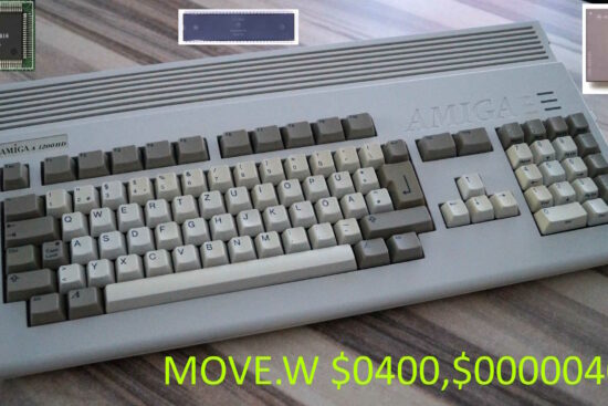
The Copper is an extremely simple processor with only two instructions: MOVE (to copy a value to 16 in a register), WAIT to wait for a position on the screen reached by the electronic brush and/or the completion of a Blitter operation (I’m simplifying here as well), and SKIP which works like WAIT but skips the next instruction if the condition is not, in fact, met.
It is thanks to Copper that it has been possible to realise various special effects on video (and not only: I used it to program the audio channels, reproducing the soundtrack of the games I worked on), by means of special programs (called Copper lists in amighist jargon) executed by this coprocessor:

The most frequently used instruction is, needless to say, the MOVE, because it allows the values of the registers of the three custom chips to be set, which is why more instructions of this type are often required for this purpose, with the associated consumption of memory and, above all, DMA slots available to read these instructions.
Reducing their number therefore brings several advantages (one can almost double the number of colours that can be changed in a video line, just to give a significant example), and a simple modification to the MOVE operation easily achieves this.
The first word (2 bytes) read by Copper is the most important one because it allows us to identify the type of instruction to be executed (I am simplifying here too). Specifically, bit #0 defines a MOVE if it is zero, or a WAIT or SKIP otherwise.
All remaining bits of the MOVE specify which register to write the value to, but currently only the first 8 (#8..#1) are used for this purpose, while the others (bits #15..#9) are not and must be forced to zero.
Since the custom chip registers start at the hexadecimal address $DFF000 and could theoretically be extended up to $DFFFFF (from $E00000 the address space is used for something else) for a total of 4kB of addressable memory area, it makes sense to reserve the first 12 bits (#11..#0) to be able to specify the starting register, while taking advantage of the last 4 bits (#15..#12) to be used to specify how many registers to set and, consequently, how many 16-bit values will follow the first.
To be even more precise, these four bits will indicate the number of registers/values, minus one. So 0 will indicate one register to be set, 1 two registers, and so on up to 15 which will allow 16 registers to be set.
In this way, the change is almost totally backwards compatible with Copper’s current operation, as the first case of the new MOVE instruction coincides exactly with what is already happening.
The almost is not placed at random, since a change must also be made to the way the SKIP instruction behaves. In fact, with the new operation, it must always read the next word (the first of the next instruction), extract the number of registers to be set and take this into account in order to calculate the address of the instruction following it in case it is a MOVE instruction.
Here again, there would seem to be no compatibility problems, except for the fact that normally the SKIP instruction requires two slots for its execution and, therefore, four clock cycles, whereas with this modification, three would be needed (it must always read the first word of the following instruction).
The solution in any case is extremely simple: simply enable the new Copper operation by using a bit in the COPCON register (which is dedicated to Copper settings), which currently uses only one bit (so there are 15 available), and that’s it.
DMA for the colours palette
Similar considerations can be made for another innovation that is as simple as it is useful for some common scenarios, namely that of loading values into the registers of the three custom chips without necessarily having to go through the Copper.
This might seem like a duplication, in light of the aforementioned modification proposed for the Copper, but it has its reasons if we make a few considerations after illustrating how it works. Which consists of setting the pointer to Chip memory (the only one accessible from the custom chips) from which to read the words (16 bits) to be written, the start register, and the number of registers to be set (which would start the operation).
Thus, four 16-bit registers are required in the register bank of such chips, but there are already several unused ones that can be exploited. In addition, a bit would be needed to indicate that this DMA channel would be free (so as to proceed with other copy operations); the DMACONR register has a couple of unused ones that could be used.
The main scenario is to be able to load the entire colour palette in one go, without duplicating resources (and bandwidth) and requiring the generation of special Copper list instructions each time. In fact, the palette is already in memory, and is read to create the appropriate instructions in the Copper list, which in turn must then be read from memory in order to actually modify the registers.
Furthermore, the previous modification to Copper is limited to a maximum of 16 editable registers (which would require more such instructions if more were to be set), whereas in this case there would be no limit. Just imagine how many Copper instructions would require a 256-colour 24-bit palette (as many as 512 words!) and, consequently, how long the Copper lists would become even when using the new MOVE instruction.
Similar considerations can be made in the case of wanting to set all the pointers to the bitplanes to be displayed, for example, or all those of the sprites, or even most of the Blitter’s registers (in the case of predefined or repetitive parts) before starting it.
Conclusions
This concludes the overview of innovations that would have been possible to improve the Amiga chipset in the graphics area (mostly), most of which are easy to implement and require few resources.
Small investments that would have had a considerable return in terms of much higher quality in the gaming field (but also in other sectors), if the company’s engineers had had a better understanding of how the platform worked but, above all, of how it was used and, consequently, how to make it evolve appropriately (satisfying the developers’ needs).
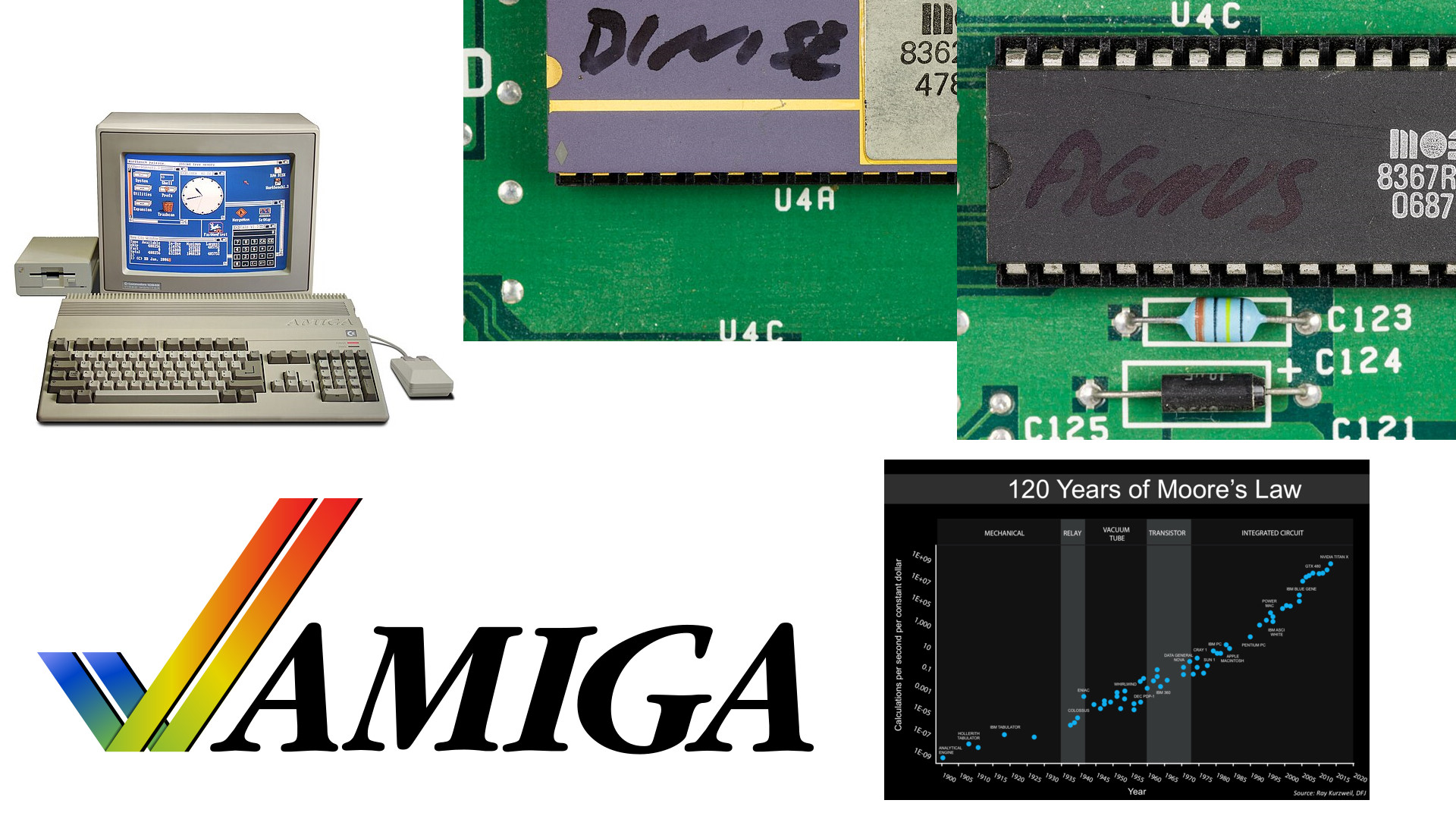
The only one that is more complicated and requires more is the doubling of sprites, but we are still talking about stuff that was already feasible in the late 1980s, thanks to advances in manufacturing processes that allowed many more transistors to be packed into the same space.
The next article will talk about innovations that would have been possible by acting on other factors.