In the previous article on ECS, I merely outlined some features that could have been implemented in this chipset and that would have alleviated somewhat the chronic lack of platform updates after the very long five years since the first version.
I refrained, however, from reporting another innovation, much more significant but still in line with the managerial dictate of “no new chips” that limited the budget of usable transistors, which would have allowed the Amiga to regain vigour and make itself extremely competitive with the competition, particularly in the videogame field.
The main problem with not having truckloads of transistors available that could be used to enhance existing features and/or add new ones, is that there are very few ways left to improve system performance.
Enlarging the data bus
The first is to increase the size of the data bus, so as to be able to read more information and thus be able to scale up in terms of usable colour depths, for example, or higher resolutions, or larger sprites, or even 16-bit audio samples instead of 8-bit, as well as read/write from/to high-density floppy disks, etc. etc.
This is the path that was taken with the next chipset, the AGA, although it was limited exclusively to certain aspects of the system (the first ones listed and which are related to the screen and graphics), leaving out others that would have equally deserved an upgrade (audio and floppy disks).
The biggest problem with this solution is that it requires several transistors to adequately expand the buffers used for the various functionalities. If, for example, you previously needed a 16-bit register to store the graphics of a bitplane, with a data bus twice as large you will obviously need one twice as large (32-bit). And so on for all other internal buffers.
It is evident that this approach is completely incompatible with the managers’ dictate, because this would have substantially increased the expenditure with regard to the number of transistors required and thus the size and cost of the chips.
Another major issue, however, was the costs that would also have risen for the production of motherboards using such chips, because larger data buses would have complicated their layout. While this might have been fine with professional systems such as the Amiga 3000 (which was the first to use the ECS and had, indeed, a 32-bit data bus), it would not have been so for cheaper systems.
Increasing the frequency
Having discarded extending the data bus, all that remains is the other solution par excellence: increasing chip frequencies. This is the solution I had thought of, but preferred not to mention in the previous article as I had not had time to research the frequencies achievable by memory chips at the time.
But having, in the meantime, clarified this point (they were available, in fact), the hypothesis of being able to run the chips at double frequency (at 14Mhz instead of 7Mhz) is not, then, so peregrine, also considering the enormous progress of the new production processes five years after the marketing of the first chipset of the Amiga (the OCS).
Specifically, the double frequency was necessary to avoid the need for multiple system clocks, which would have complicated the platform and implementation. From this point of view and having only one “master clock” the problem is solved (also because all the necessary clocks, derived from the 28Mhz one, are already present: those at 14 and 7Mhz).
The problems of the doubled clock
Using a multiple clock of the main clock does not solve all problems, unfortunately. One cannot, in fact, think of doubling the clock used to access the memory and hope that magically the whole system will work.
Specifically, the most critical part is the video subsystem, represented mainly by the circuitry that actually displays the graphics taken from Chip memory (the only one usable by custom chips). But even the DMA controller (which orchestrates the memory accesses of all the chips) would not function properly as it is, working at double the frequency.
In order to understand what we are talking about and these issues, it is necessary to do a little excursus on how all the DMA channels and, therefore, the memory accesses (from now on it will be implicitly assumed that it is that Chip) work when a video line (called a raster line, in jargon) is processed, showing the relative diagram (taken from the famous Amiga Hardware Manual. For purely didactic purposes):
A raster line consists of 227.5 “colour clocks“ (one colour clock is equal to two system clock cycles), which also represent the slots available for memory access, depending on the particular use (memory refresh circuitry, disk, audio, sprites, and screen graphics).
Video circuitry
The problematic part concerns the screen graphics (because in all the others, the slots for the particular functionality/channel are fixed: either you use them or you don’t), as they are variable depending on the horizontal resolution (high or low), size (in the case of overscan, for example) and the depth of the screen (number of colours = number of bitplanes to load data from).
Without going into too much detail, suffice it to say that the mechanism by which the graphics are displayed is based on two collaborating elements/chips: Agnus, which arbitrates memory accesses and thus reads or writes data to/from the individual DMA channels, and Denise, which takes the read data and processes it by sending it to the TV or monitor.
It is from the precise collaboration between these two chips that we can see the result of this synchronisation on the screen. To be more precise, Denise needs all the data it needs to have been read, so that it can start with the pixel display.
From the diagram above, towards the centre/right, we can see how Agnus starts reading all the data it needs from slot $38, ends up at slot $40 (where it starts reading those of the next block), while Denise only starts sending the processed pixels to the screen from slot $45 (because it had to wait until $40 to get all its data).
Operating at 14Mhz instead of 7Mhz, a raster row will consist of 227.5 * 2 = 455 colour clocks/slots. So there are twice as many slots available to access memory. While there are no problems for memory refresh, disk, audio and sprites, which can use the slots at the same positions, there are problems for screen graphics.
In this case, in fact, one can no longer start from slot $38 to read the data, but it should from $38 * 2 = $70. Also, one must wait for slot $40 * 2 = $80 to start processing them. While they will start to be displayed from slot $80 + 5 = $85.
The problem only arises with low resolution (320 horizontal pixels. Overscan excluded), as Agnus will have finished reading the data of the 8 (at most) bitplanes already at slot $70 + 8 = $78. Denise, however, cannot use them immediately, but will have to wait for slot $80 (otherwise it will start displaying the graphics 16 pixels to the left).
To make things right, two blocks will have to be added. One block for Agnus, which will stop for 8 slots after it has finished fetching the data from the 8 bitplanes, so that the next 8 are not read immediately, as they are not needed immediately (Denise takes twice as long to process the pixels in low resolution).
The other block concerns Denise, which in low resolution will have to wait for a clock cycle immediately after processing a pixel. This is necessary as, operating now at twice the frequency (compared to OCS), it takes half the time to send the pixel to the monitor/TV. So it is forced to wait a cycle before moving on to the next pixel.
Things go wonderfully well for high resolution, on the other hand. This is because it is possible to recycle how OCS works on low resolution and do exactly the same way, without adding any block. In this case, Agnus will start reading data at slot $78. It will finish at $80, from which Denise will start processing. Finally, the first pixel will be displayed at $80 + 5 = $85.
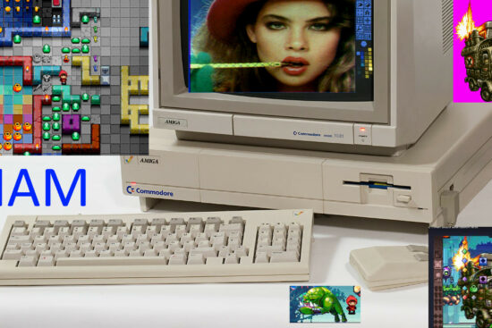
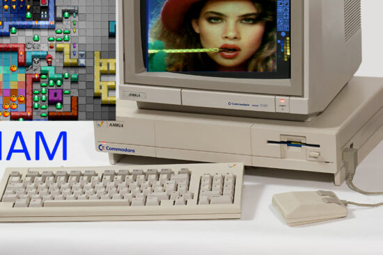
In addition to this, the considerable advantage with the high resolution is that it will be able to use 8 bitplanes instead of 4, thus enabling the display of up to 256 colours on screen, including EHB (64 colours), HAM (4096 colours), and Dual Playfield modes.
Other necessary adjustments
Some minor modifications will be necessary for sprites, however: their horizontal position have to be internally doubled when the screen is working in low resolution. This is for the same reasons that Denise needs to wait for a clock cycle after processing a pixel.
Without this modification, a sprite would be displayed in high resolution, thus with half the width, generating an obvious visual artefact.
A similar modification applies to Copper, and more specifically to the two WAIT and SKIP instructions, which respectively allow you to wait for a certain screen position before continuing execution with the next instruction, and to skip the next instruction if you have already reached or passed a certain screen position.
The changes are necessary because there is no room to add an extra bit to make the selection of the horizontal position to be controlled or reached wider, so the Copper will work exactly the same as for OCS (which means always ‘moving’ horizontally by 4 pixels at a time in low resolution).
Finally, Paula. This chip (which has never been touched: it has remained the same in all Amiga chipsets) also needs a similar modification, specifically for disk management. In fact Paula takes care of reading or writing data to/from the floppy disk. This happens at a certain speed in the OCS, but operating with double clocking requires, in this case, that the frequency for these operations is halved, so that it works exactly the same as with the OCS.
How to implement
To select the 14Mhz clock instead of 7Mhz, it is sufficient to take advantage of a single free bit in one of the many available registers. The solution that guarantees the best OCS compatibility is the new BPLCON3 register, which was introduced with the ECS.
As can be seen in this description, the new register only works if it has been enabled, i.e. by setting bit 0 of the BPLCON0 register. At this point, any bit of BPLCON3 could be used to enable the double-frequency clock: for example the number 3.
Then only when both this bit and bit 0 of BPLCON0 are set to 1 will all the custom chips (excluding the two CIA chips that handle I/O, which continue to operate in the same way) run at 14Mhz and the above changes will be operational. Otherwise everything will work exactly the same as for OCS, ensuring full compatibility with all existing software.
The Blitter on steroids!
Operating at 14Mhz also results in a performance improvement, as screens working at the same colour depth require half the slots to take up their data, leaving the others free for use by other devices: CPU, Copper and Blitter.
This is exactly what also happens with the AGA chipset, when it is working with FMODE 1 or 2. Better still with FMODE 3, of course, but this operation cannot be emulated by the modifications I have suggested (you would also need a 32-bit bus).
It wouldn’t be a problem in any case, since the 14Mhz mode also extends to the Blitter, which in the AGA remained at 7Mhz. This means that the 14Mhz ECS is able to move far more graphics around on the screen than the AGA with FMODE of 3. Compared to the OCS, it’s as if the Blitter is travelling at 2½ to 3 times the speed.
Virtually all OCS games that were developed for the Amiga could always run at 60/50Hz, and very often with more colours and/or more detailed graphics (in this case using Dual Playfield mode in high resolution, for example. As well as EHB).
You can, therefore, easily imagine what could have been achieved with such a fast Blitter. For the Amiga it would have meant to be absolutely competitive again with the gaming platforms of the time, so consoles and PC included (except for 3D games with textures, which would come later though).
No compatibility problems
A Blitter operating at 14Mhz seems to have also been hypothesised for the chipset following the AGA, the AA+, but this solution would have appeared impracticable due to compatibility problems with existing software.
In reality, and as we have seen, the 14Mhz clock is only selectable by activating the two aforementioned bits. This means that games or demos that start at system start-up would find themselves with the chipset set to OCS mode, and would therefore run without any problem.
Those, on the other hand, that take control after the system start-up should take care to set the system correctly before taking full control. In particular, by invoking the LoadView API and passing a null pointer, the s.o. would set the chipset registers back in place and the application could then change them as it saw fit.
Conclusions
I think it is clear that these simple changes (combined with those suggested in the previous article) would have allowed the ECS to get back on track and make itself much more competitive, giving the Amiga platform a new youthfulness that not even the later AGA would have brought (unless it too had introduced a 14Mhz clock for all chips, as I have outlined. Which, however, did not happen), all while staying within the terms of the budget imposed by management (“no new chips“).
The new ECS platform would have been slightly more expensive, due to the use of a 68000 processor operating at 14Mhz (taking a 16Mhz one. Or a 12.5Mhz one overclocked to 14) and for faster memories (at 140ns).
But in the latter case 1MB of standard equipment would have been adequate for the needs of the times, with the expansion slot (Trapdoor in Amiga jargon) capable of expansion in any case, just as was the case with the Amiga 500 (which was sold with 512kB. To which many later added another 512kB).
I don’t know if this would have helped changing the fortunes of the Amiga, because we are still talking about hypothetical scenarios. But, with that kind of management, I don’t think Commodore would have lasted very long, anyway…


